
You Might Like
-
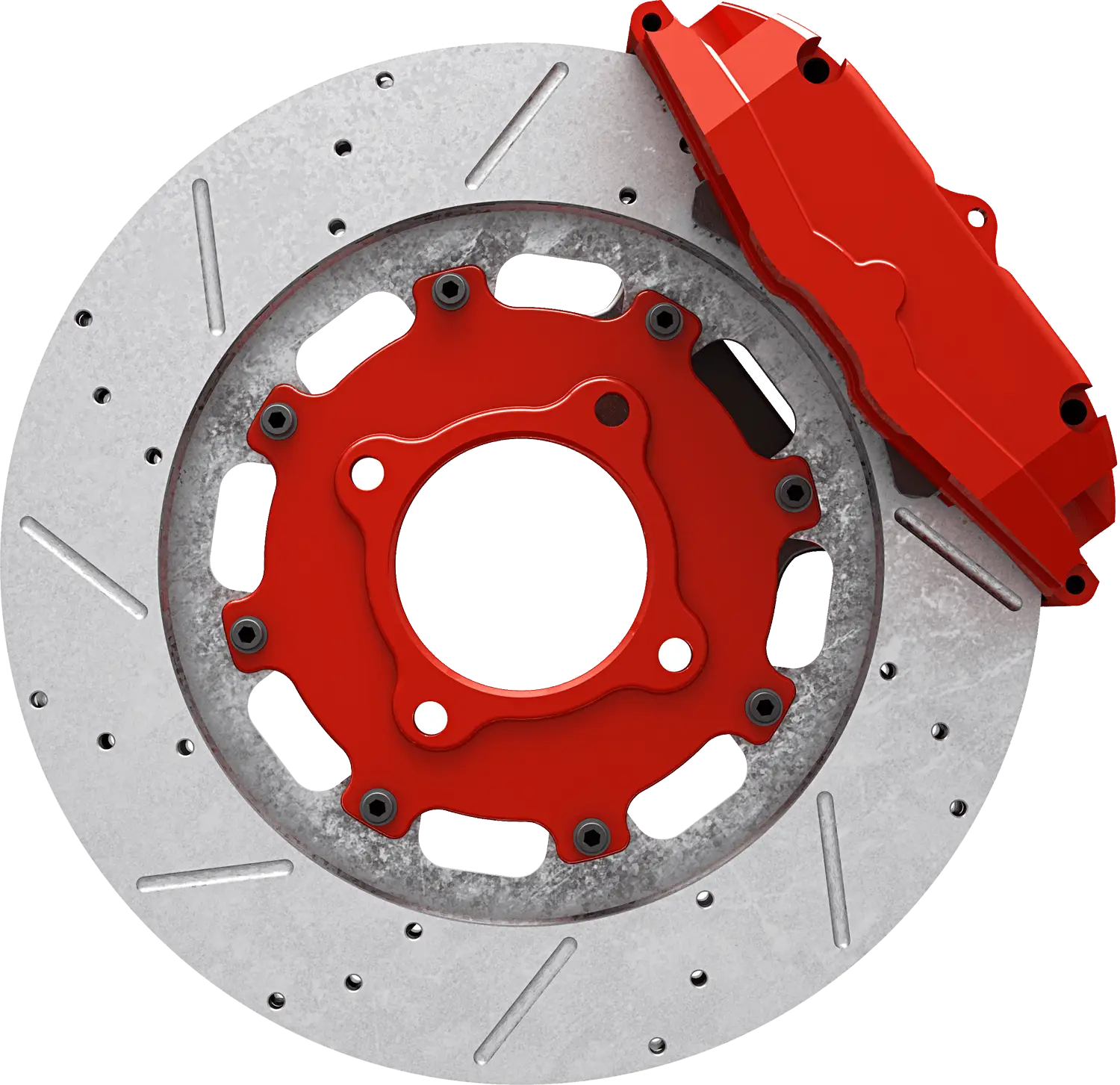
Red Brake Disc Automotive Part -

Black Smartphone Back View Design -
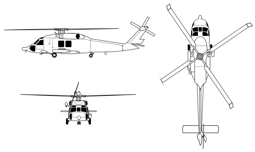
Helicopter Design and Outline Illustration -
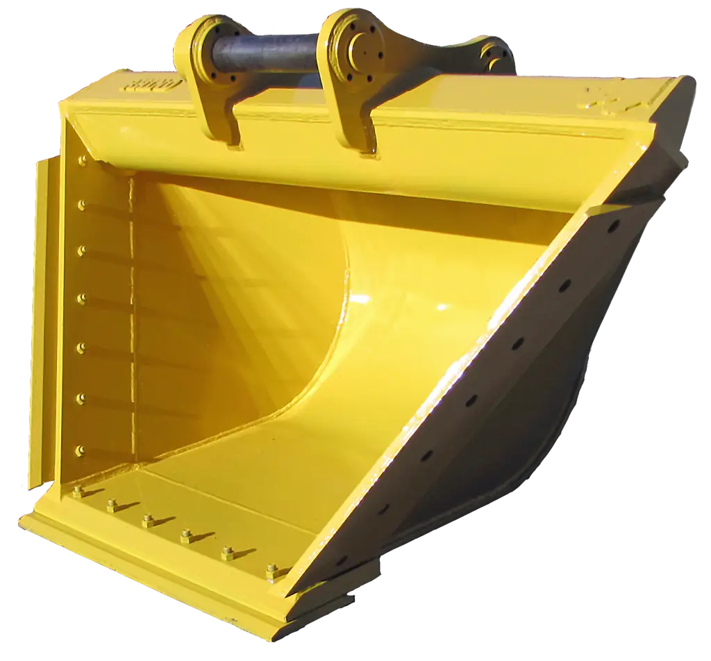
Yellow Excavator Bucket for Construction -
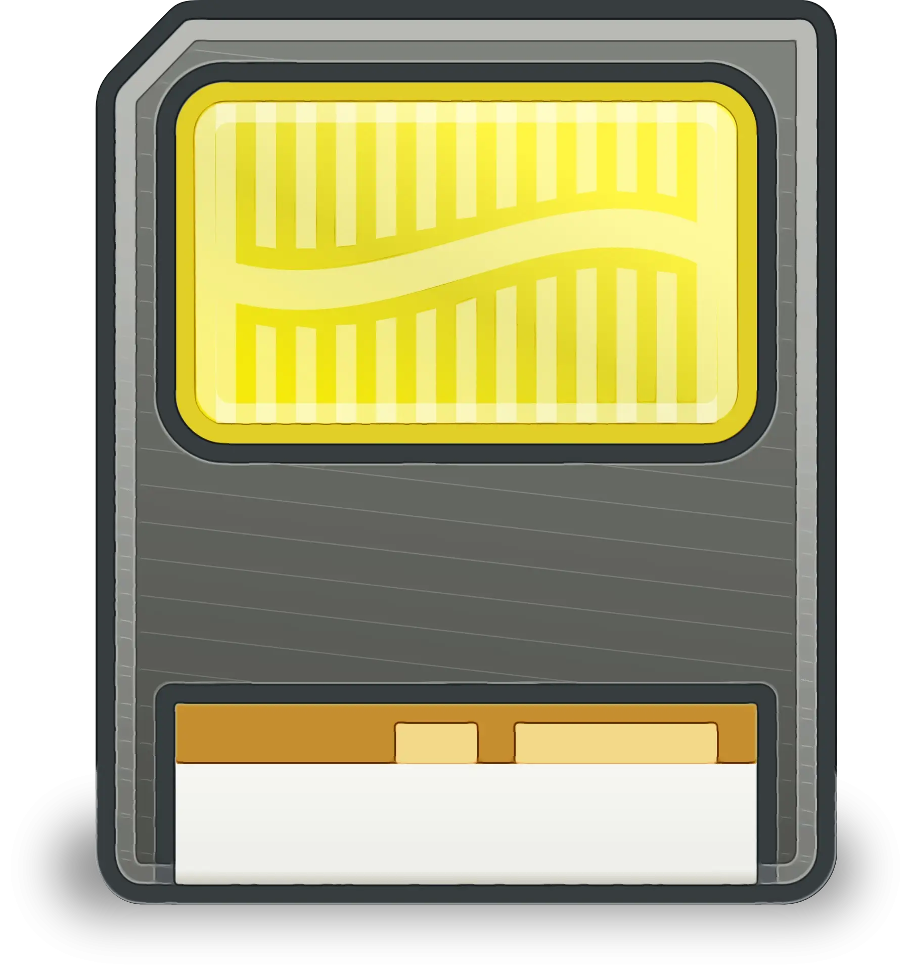
Illustration of a Memory Card -

Power Button Icon in Bold Black -

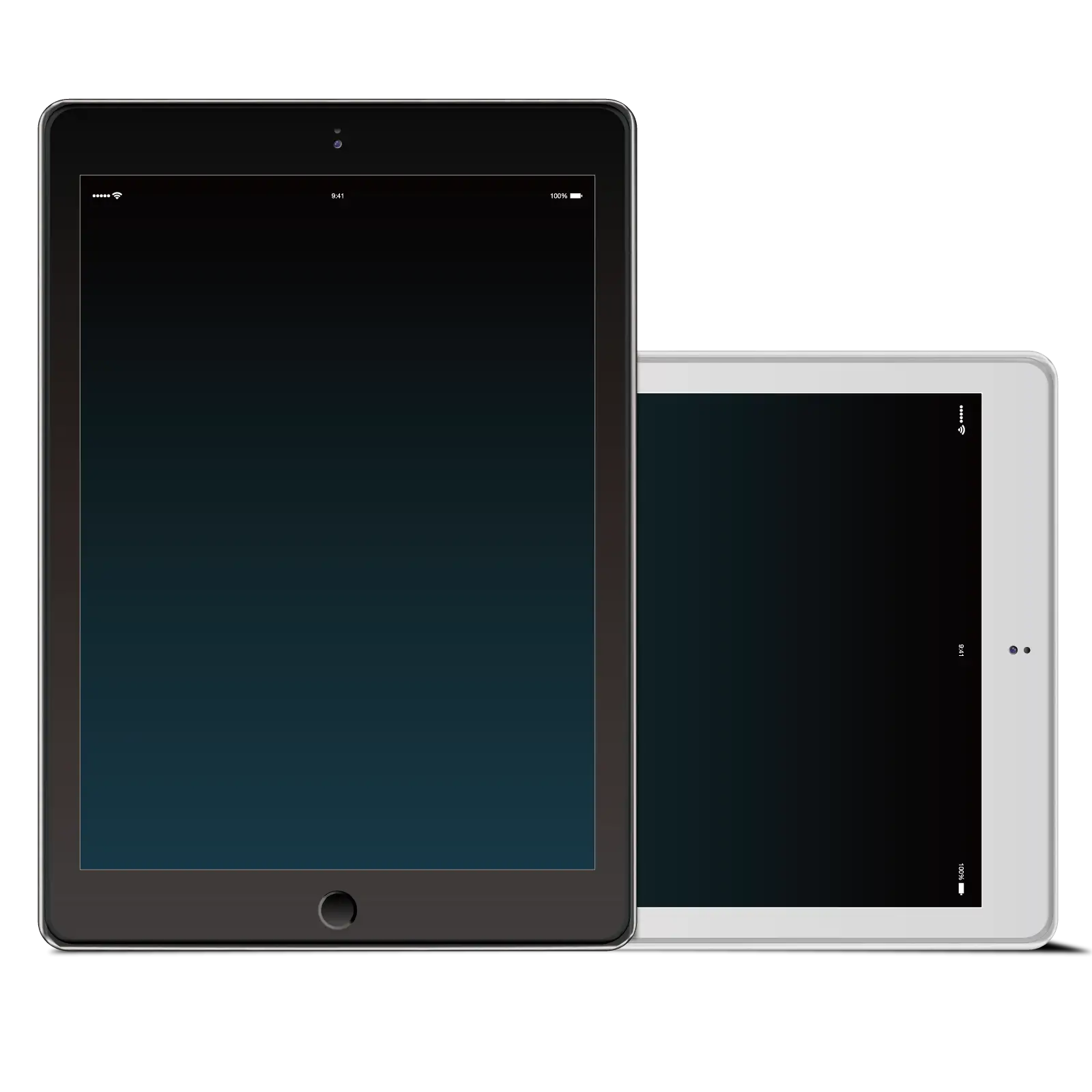
White Digital Tablet with Sleek Design -

SMC Corporate Logo Design -

Sleek Black Flat Screen Television -

Hand Using Black Computer Mouse -
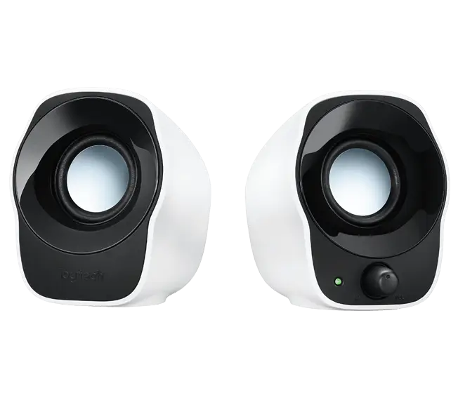
Compact Speakers for Clear Audio Experience -
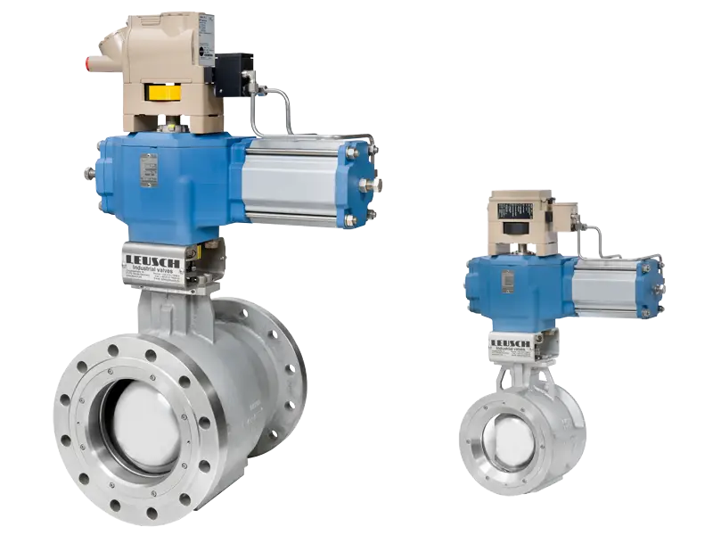
Industrial Valve System Design -

Black and White Gears Icons -
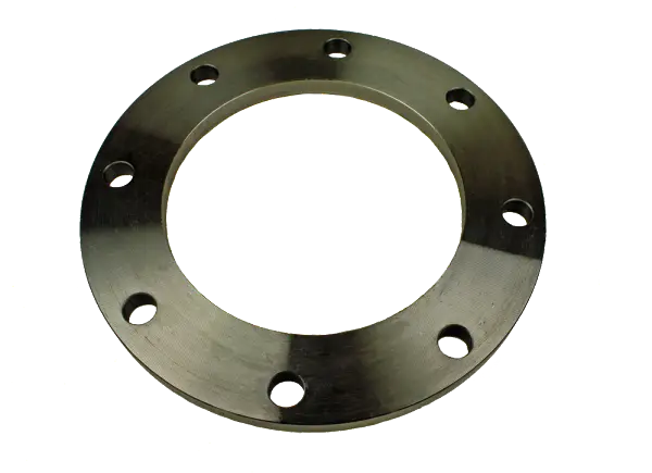
Metal Flange with Holes -
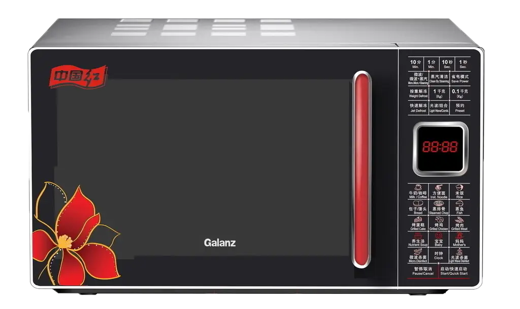
Modern Microwave Oven -
Black and White Tablet Device Icon -
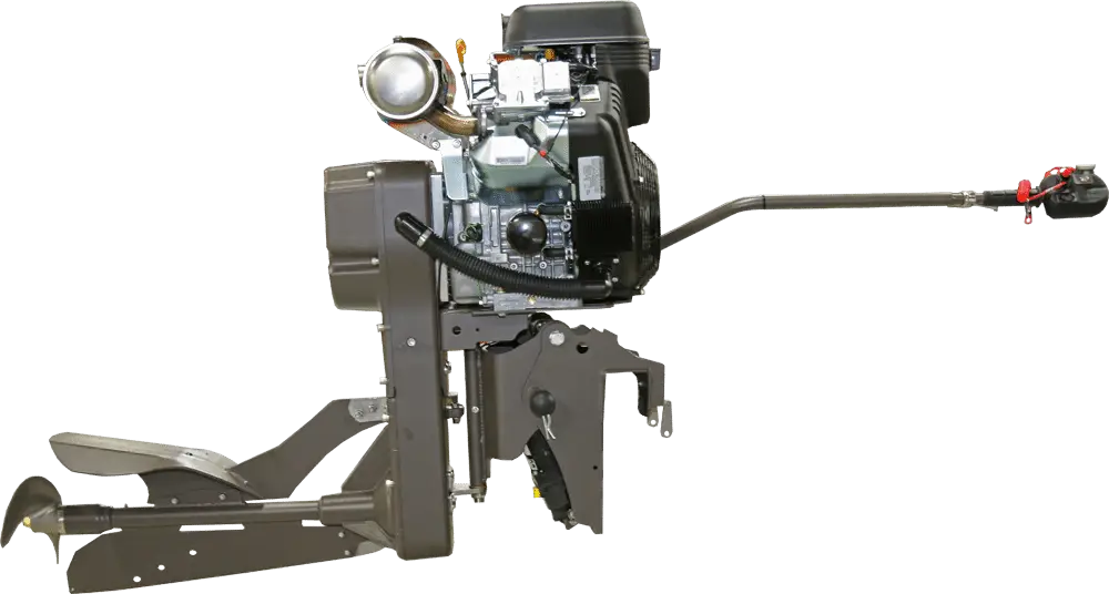
Powerful Engine Machinery -
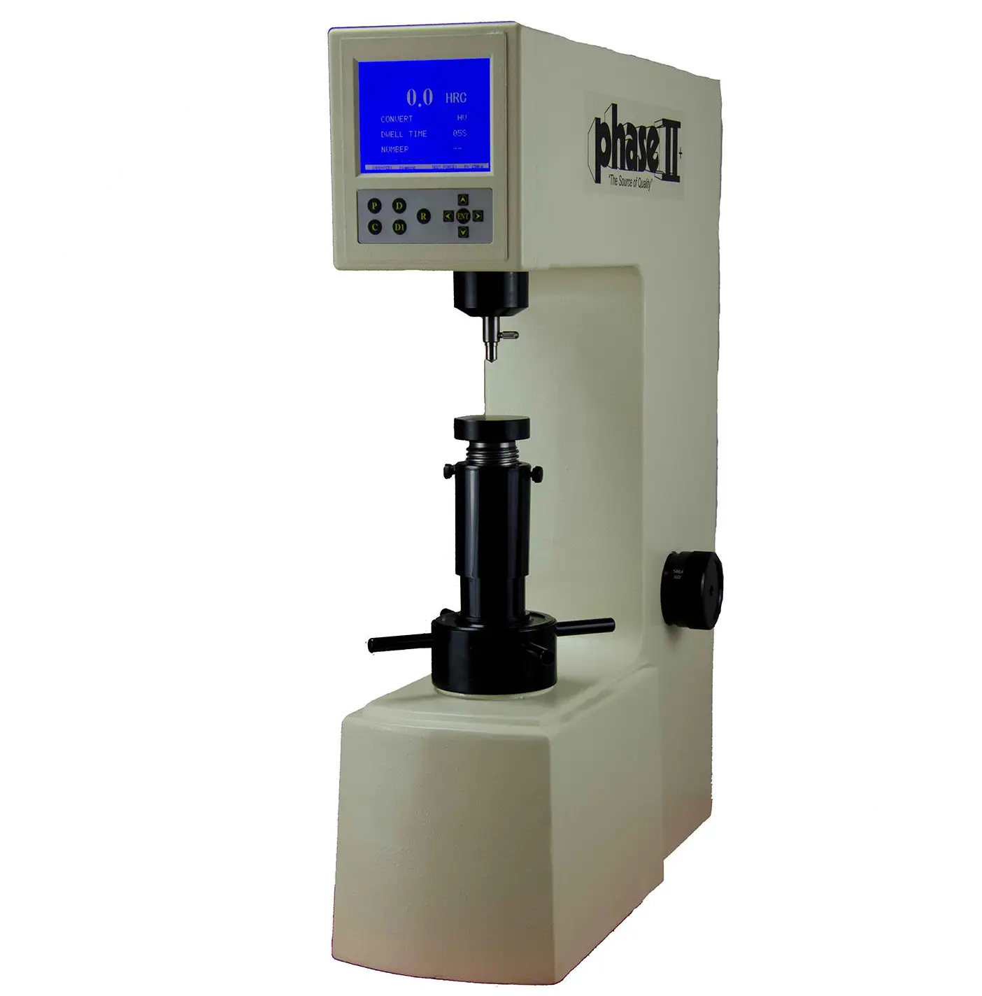
Precision Hardness Tester for Materials -
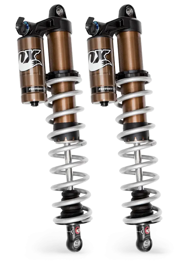
Fox Shock Absorbers for Off-road Vehicles -
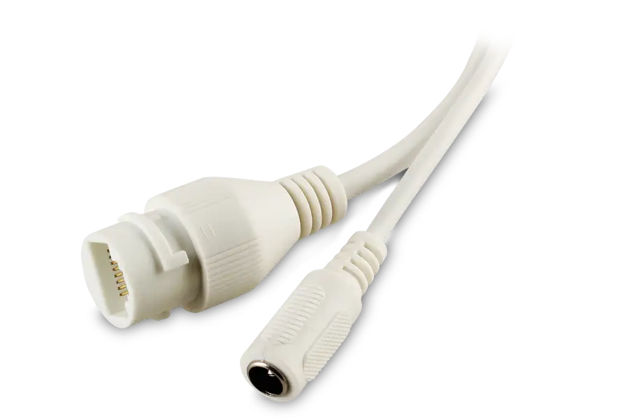
White Cable Connector for Technology Devices -

Set of Car Parts Icons -

Steampunk Mechanical Wings -
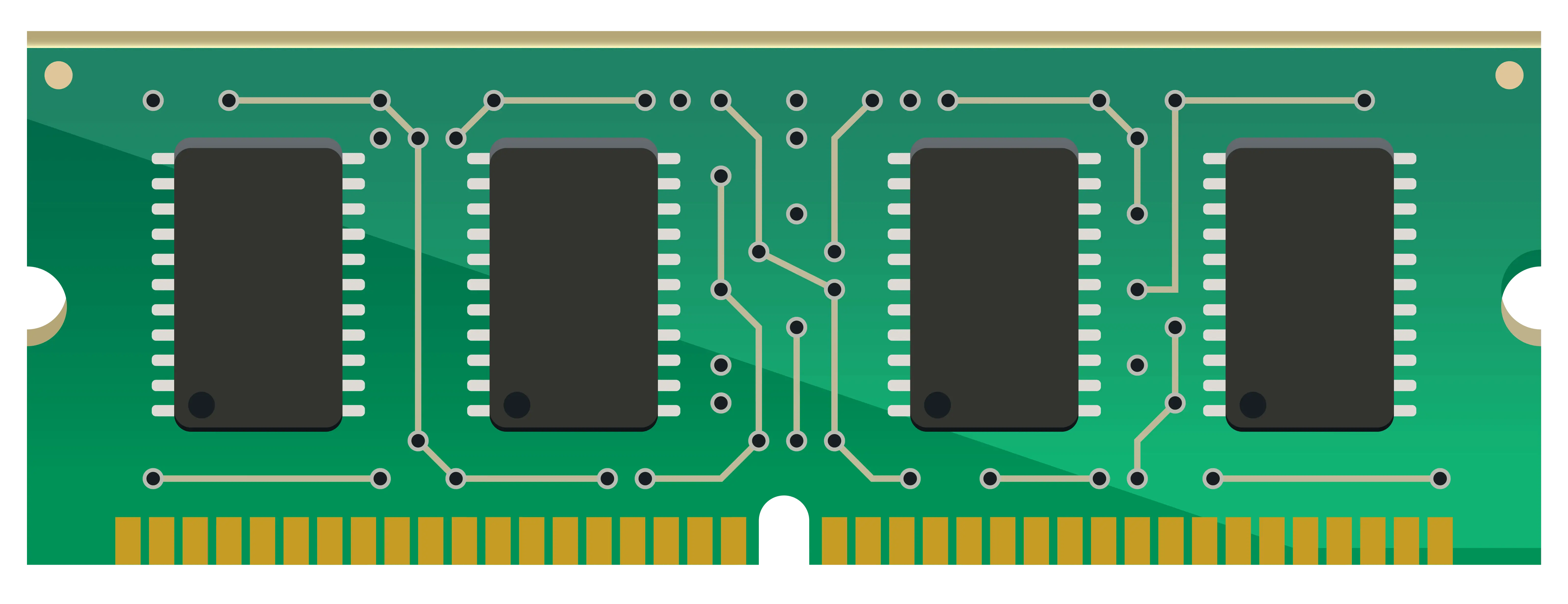
Green RAM Memory Module -
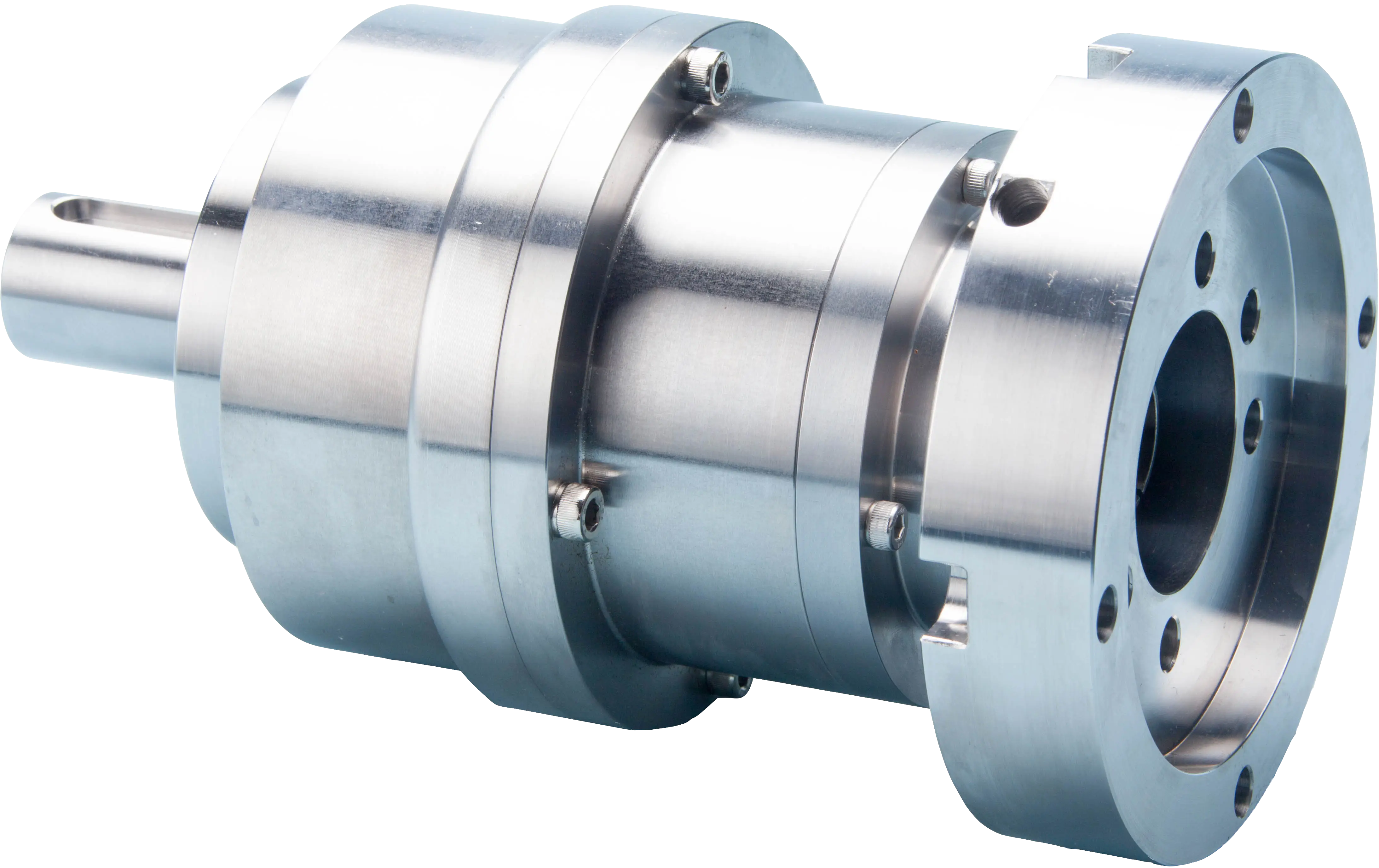
Precision Metal Gear Reducer for Industrial Use -

Colorful Oil Pump Jack -
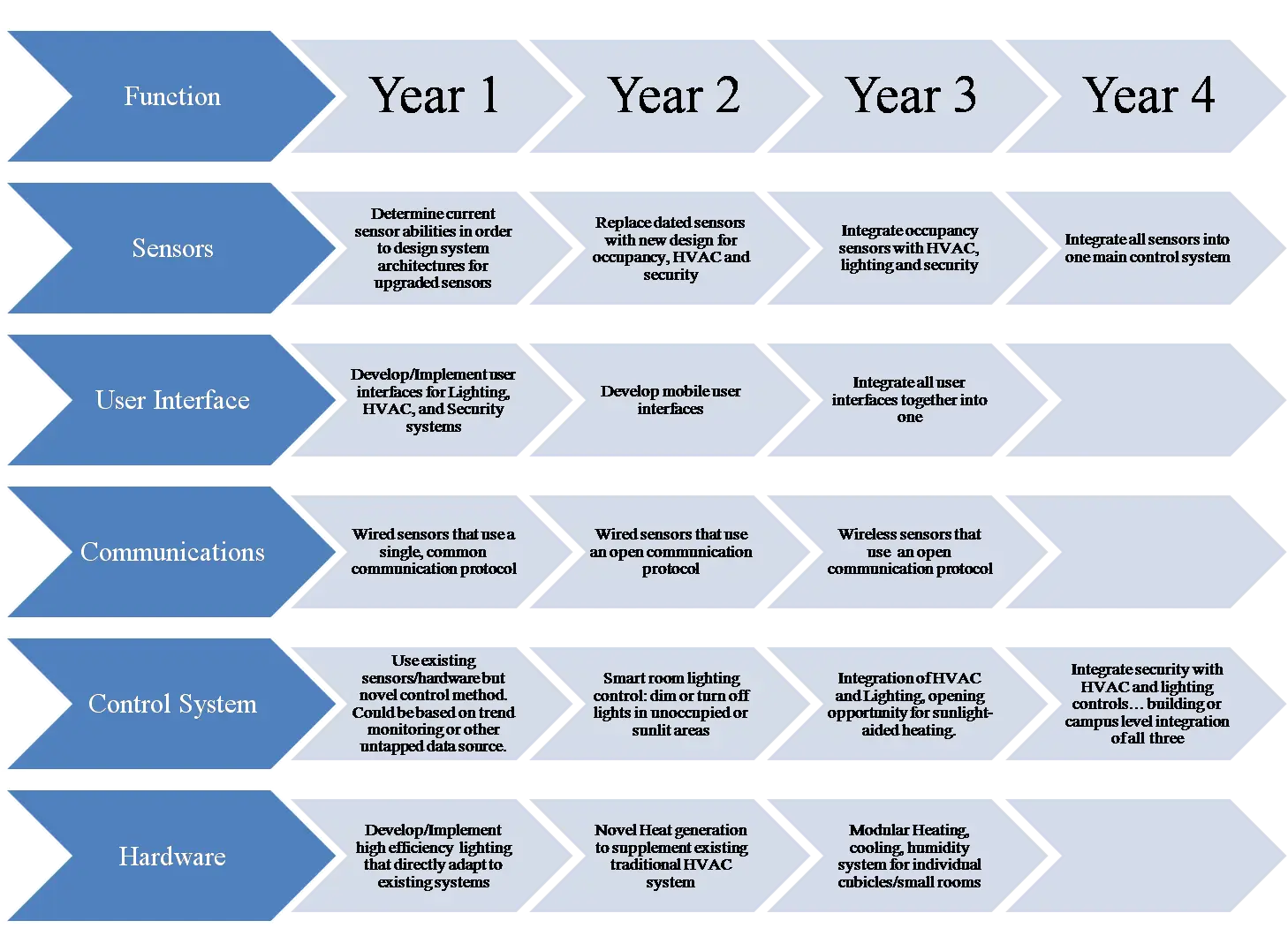
Development Roadmap for Project Planning -

Assorted Office Supplies and Gadgets -

Samsung Smartphones in Black and Blue -
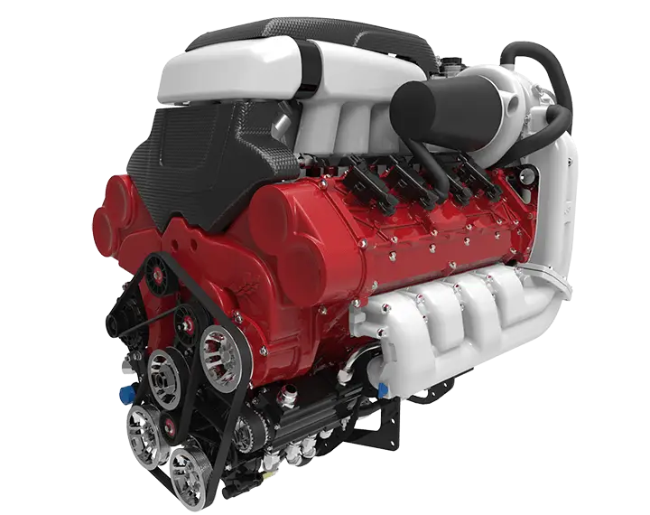
Powerful Engine Machine -
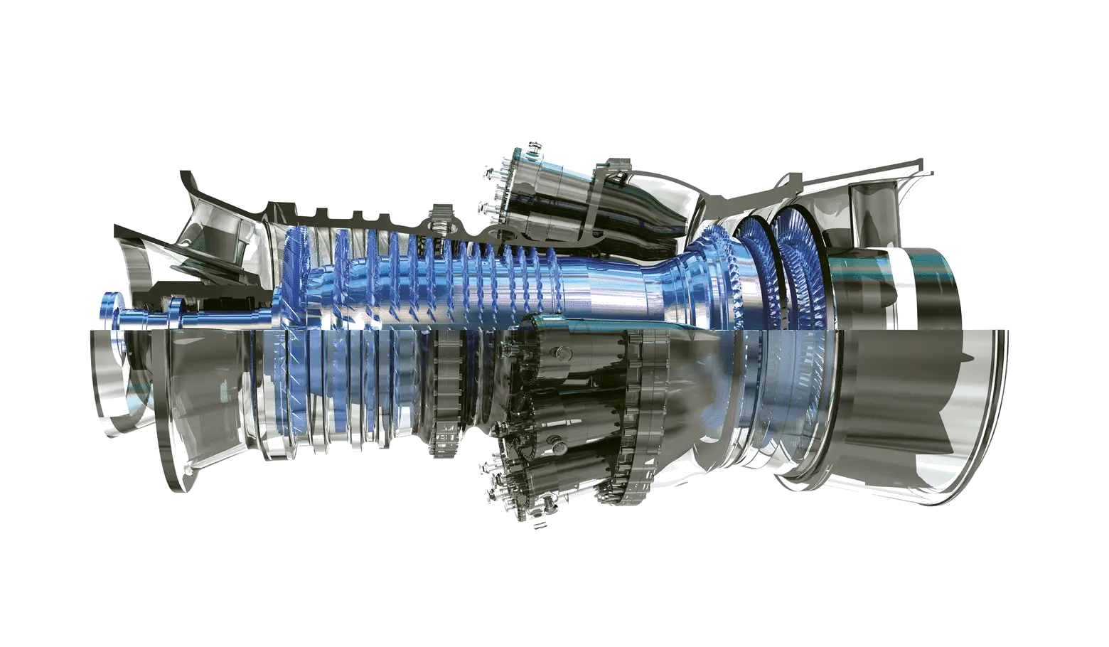
High-tech Engine Turbine System