You Might Like
-

Colorful Broom for Cleaning -
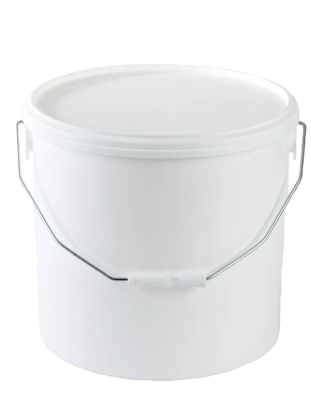
White Plastic Bucket with Handle -
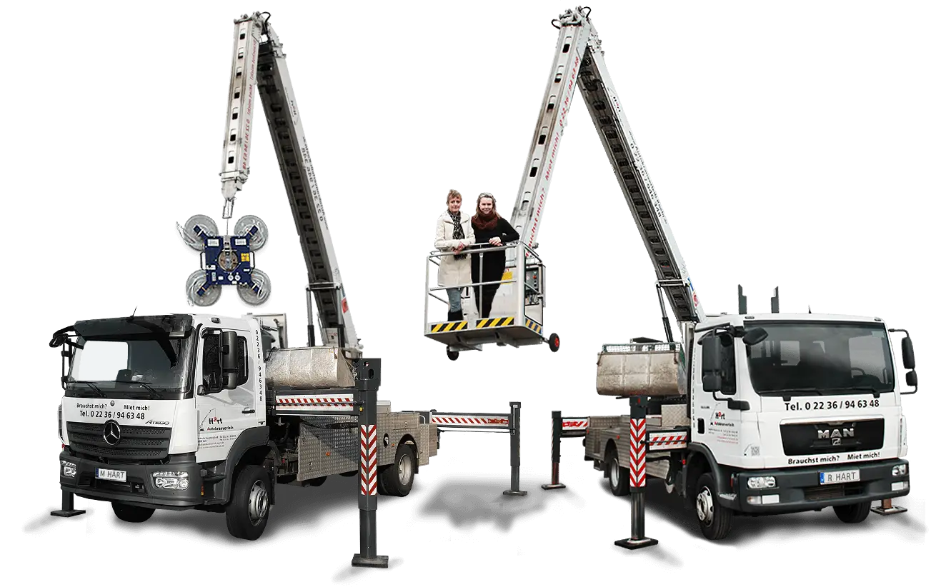
Lift Trucks for Construction -
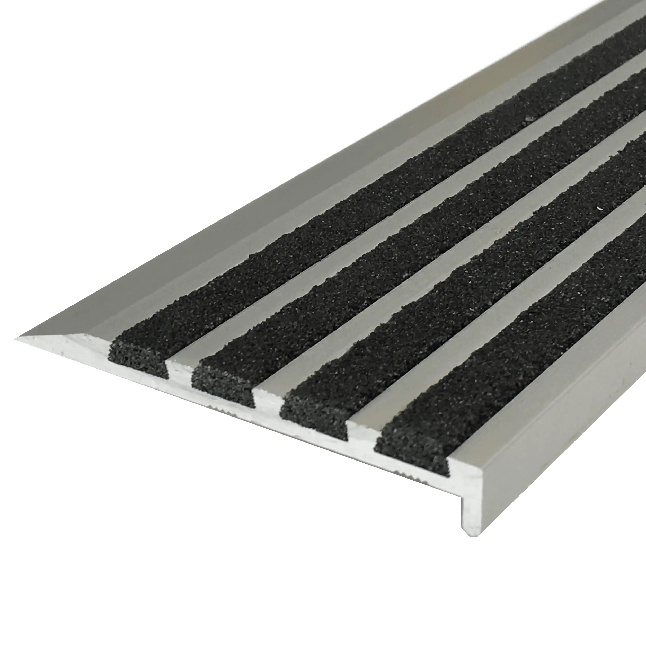
Durable Stair Nosing for Safety -
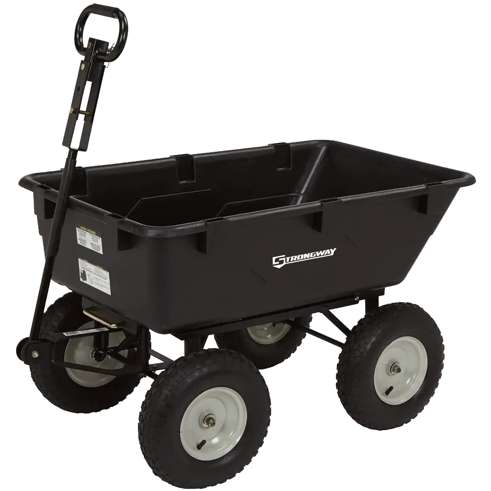
Black Garden Cart with Handle -
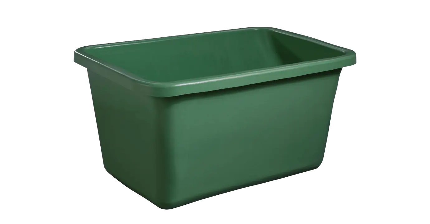
Green Plastic Bin for Household Storage -
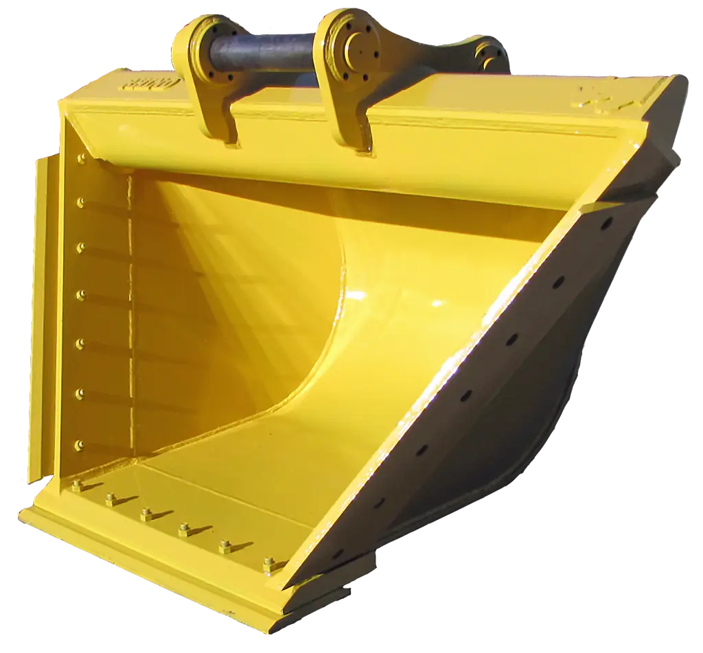
Yellow Excavator Bucket for Construction -
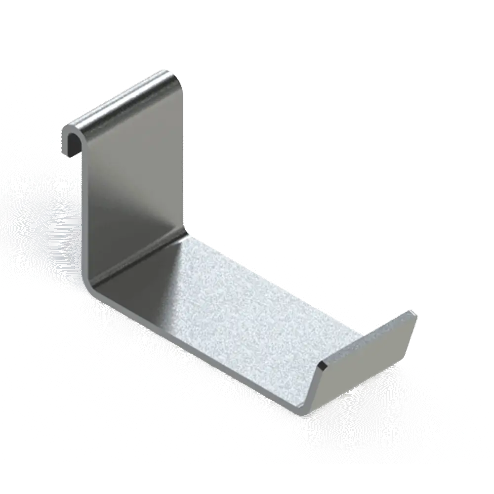
Metal Hook for Hanging -

Modern Toilet Fixture with Flush System -
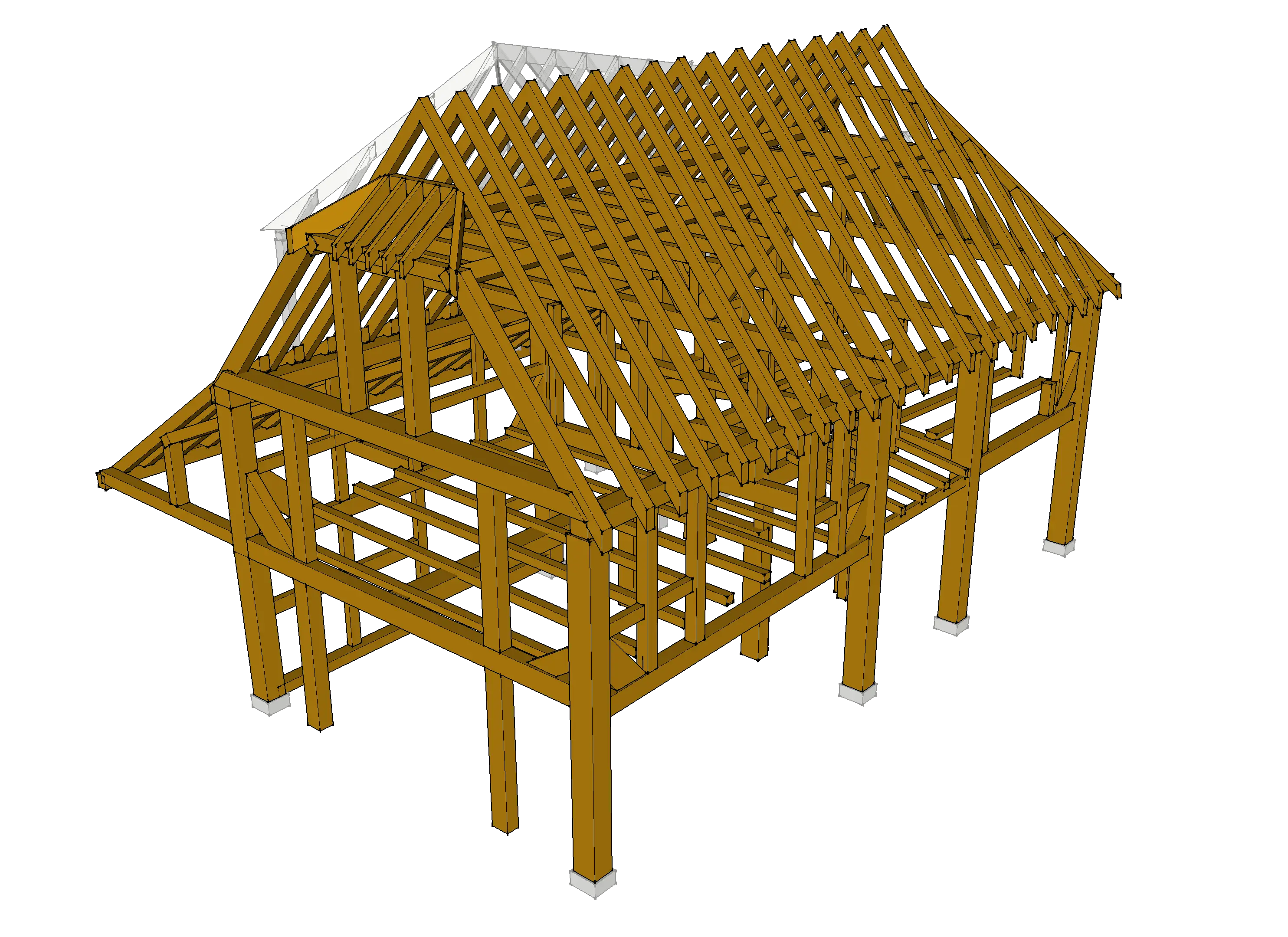
Wooden House Frame for Construction -
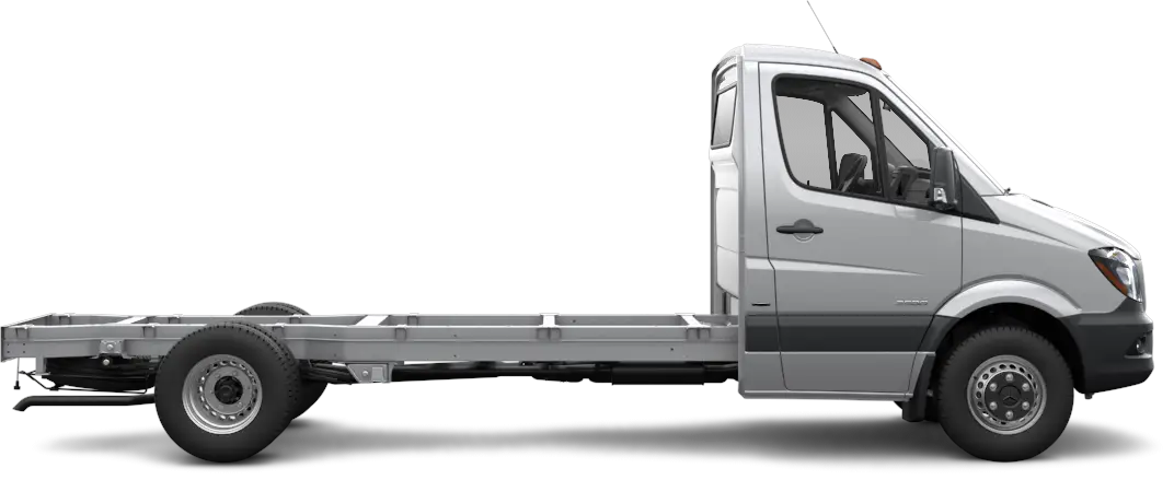
Minimalistic Chassis Truck Vehicle Frame -
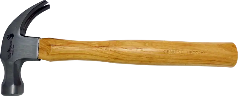
Hammer with Wooden Handle -

Cartoon Worker with Ladder and Tools -

Red and Black Handheld Power Drill -
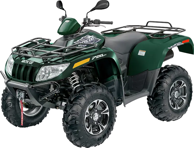
Green All-Terrain Vehicle for Off-Roading -
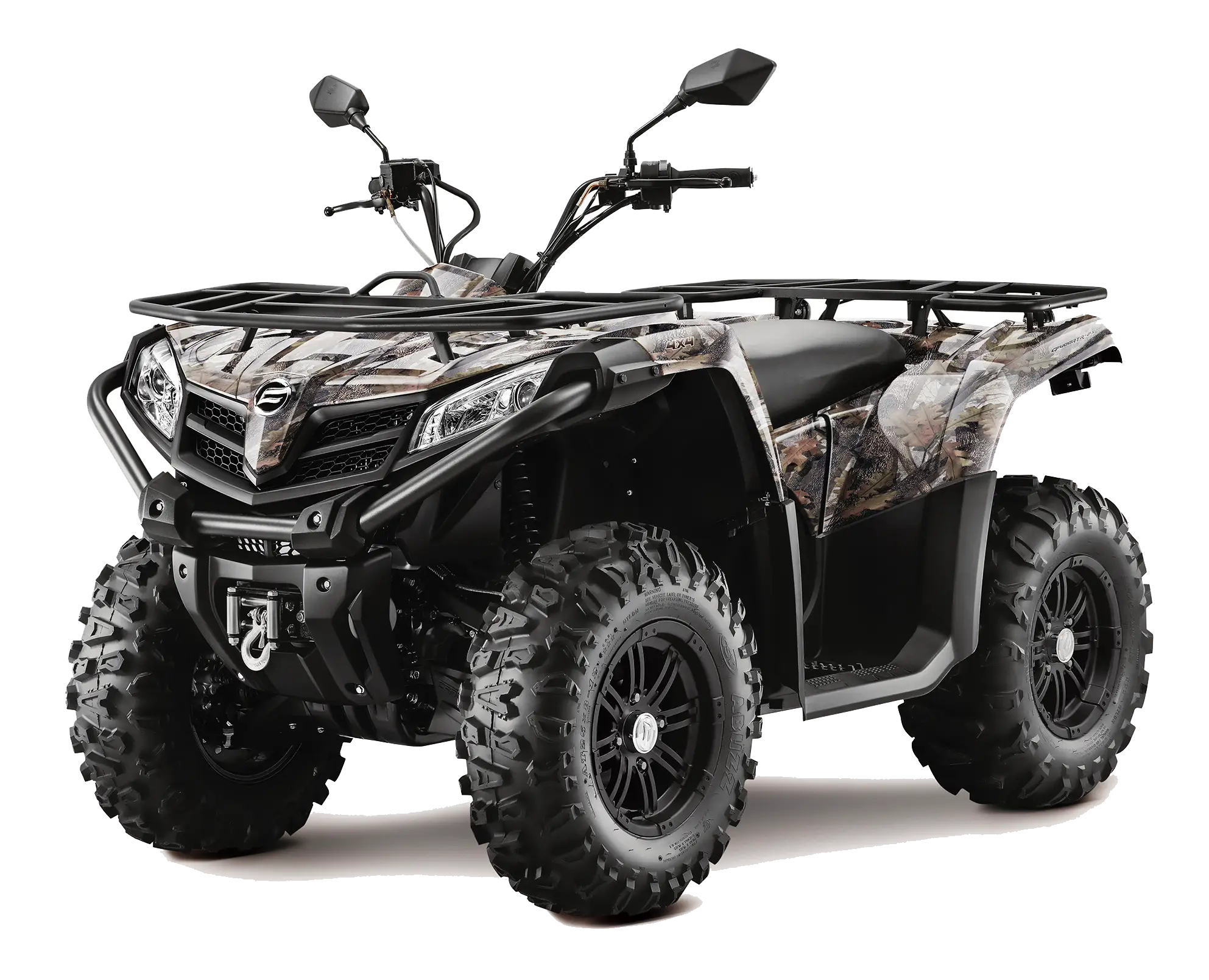
Camouflage All-Terrain Quad Bike -

Orange Traffic Cone for Road Safety -
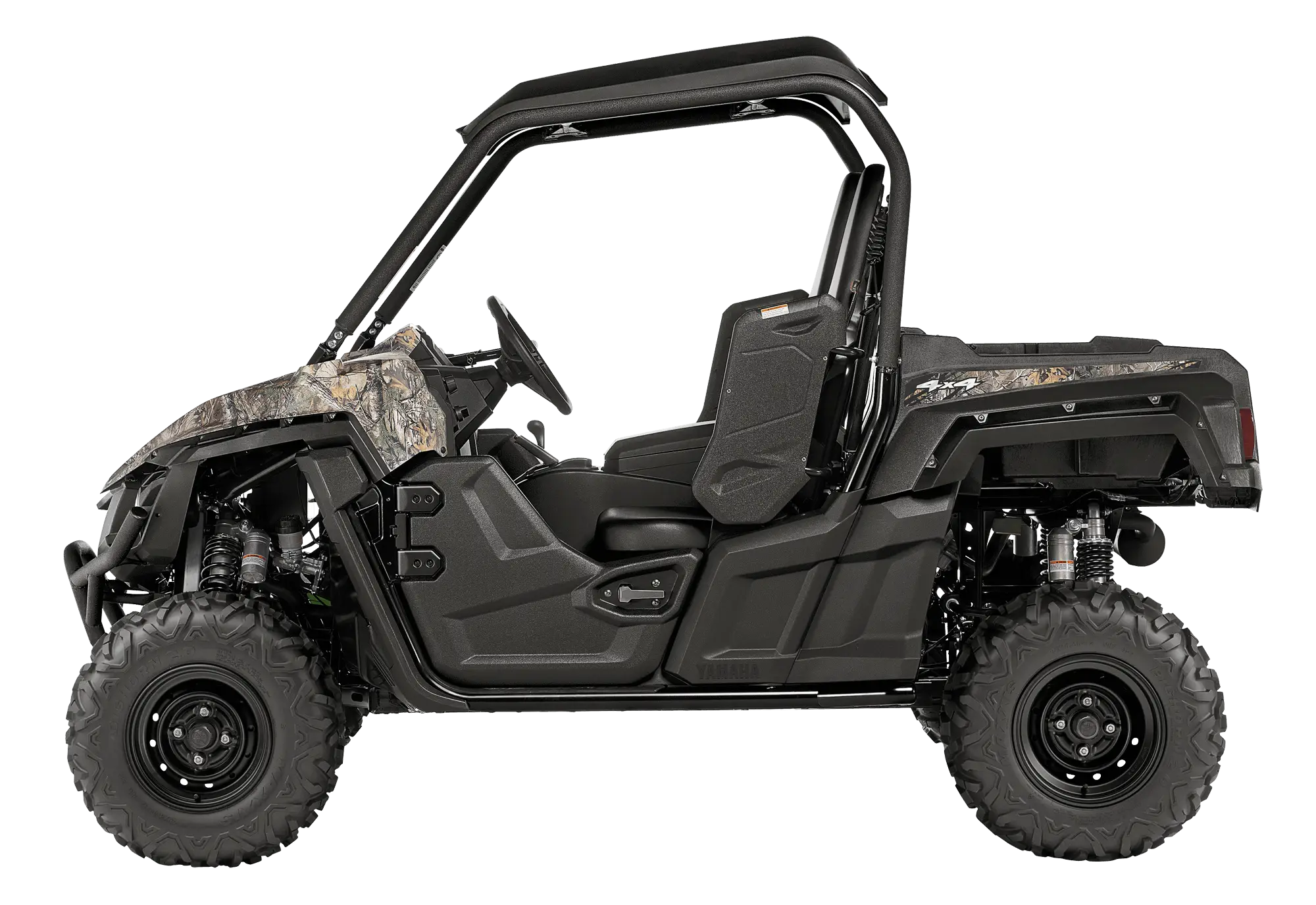
Black UTV for Off-Road Adventures -

Work in Progress Sign -

Large Water Tank for Storage -

Wrench and Screwdriver Tools -

Wooden House Frame Structure -

Metal Bolt for Fixing -
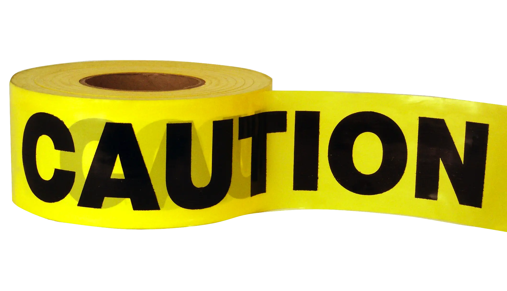
Yellow Caution Tape -

Construction Worker with Trowel in Hand -
Yellow Excavator for Construction -
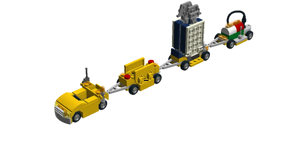
Lego Toy Train -

Digestive System Diagram -

HR Workflow Diagram -
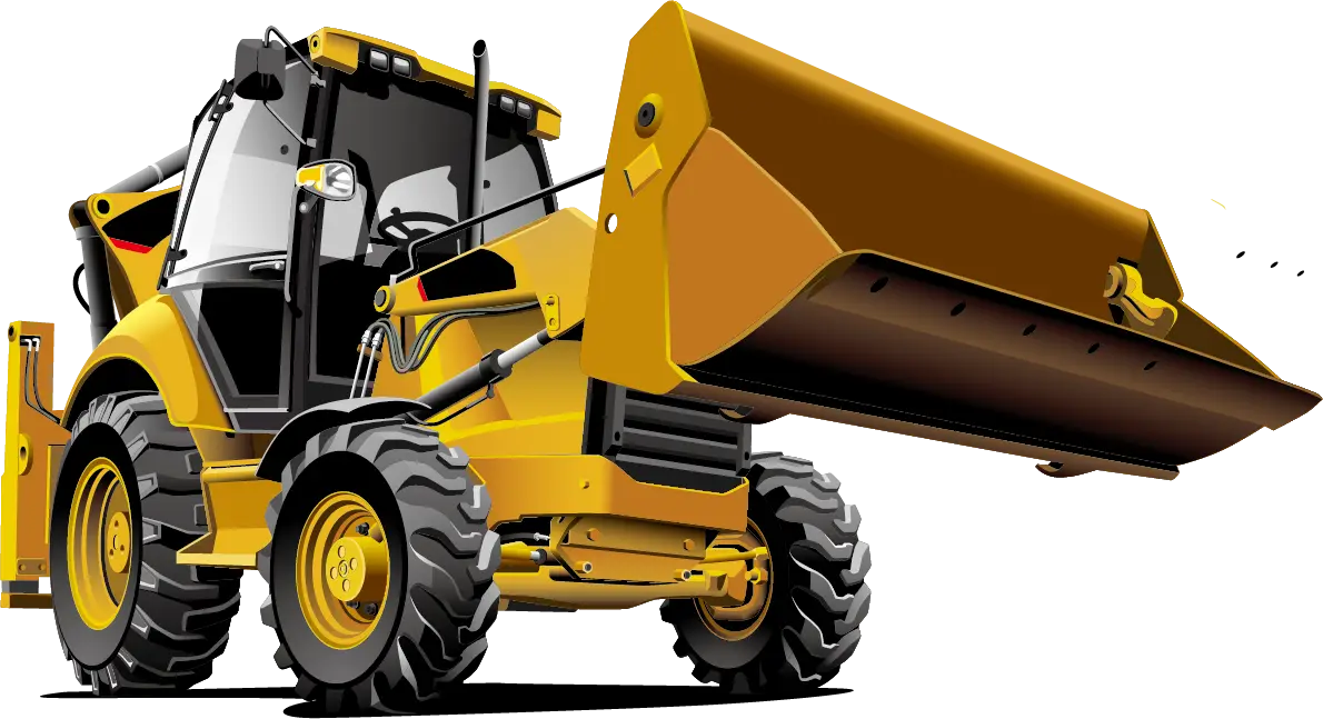
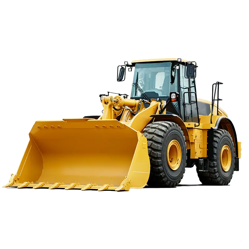
Yellow Bulldozer