You Might Like
-
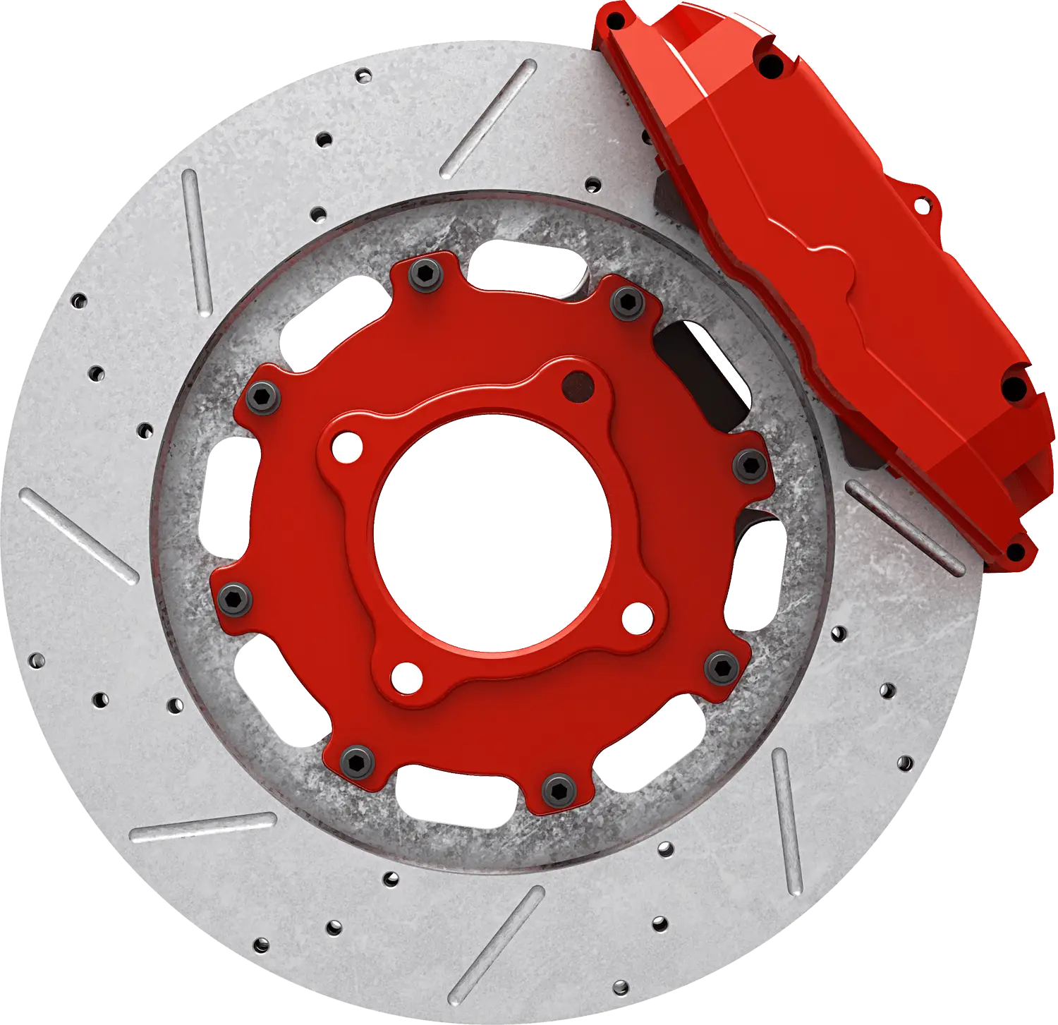
Red Brake Disc Automotive Part -
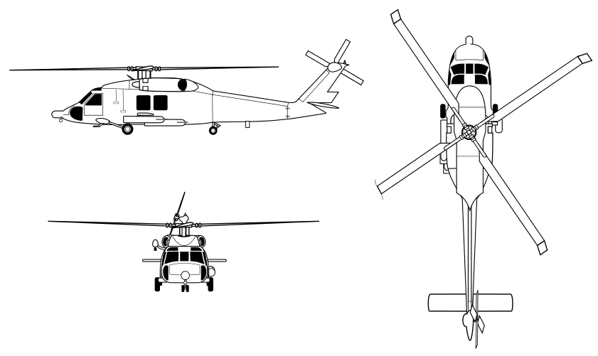
Helicopter Design and Outline Illustration -
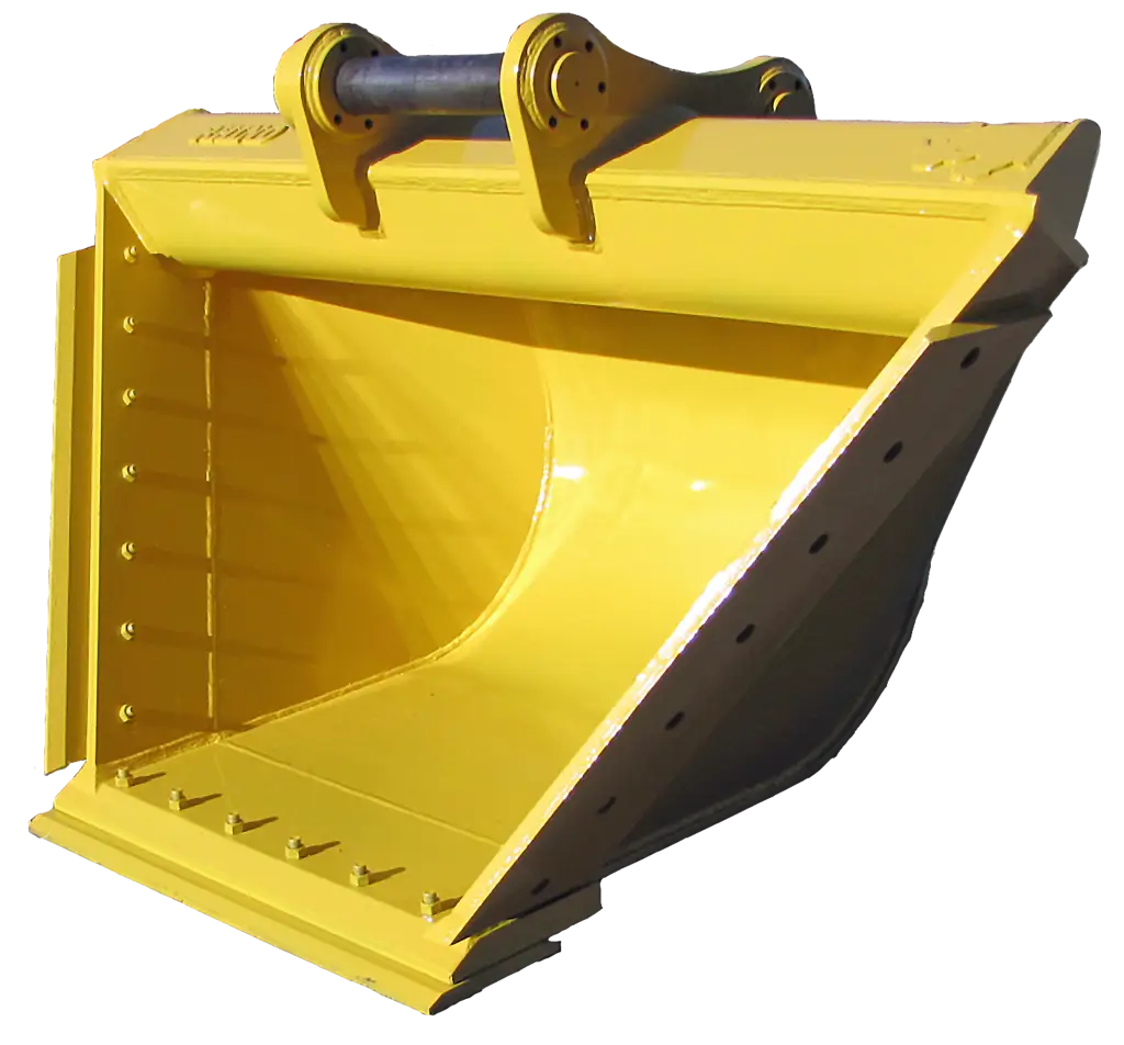
Yellow Excavator Bucket for Construction -

Futuristic Robot Head -

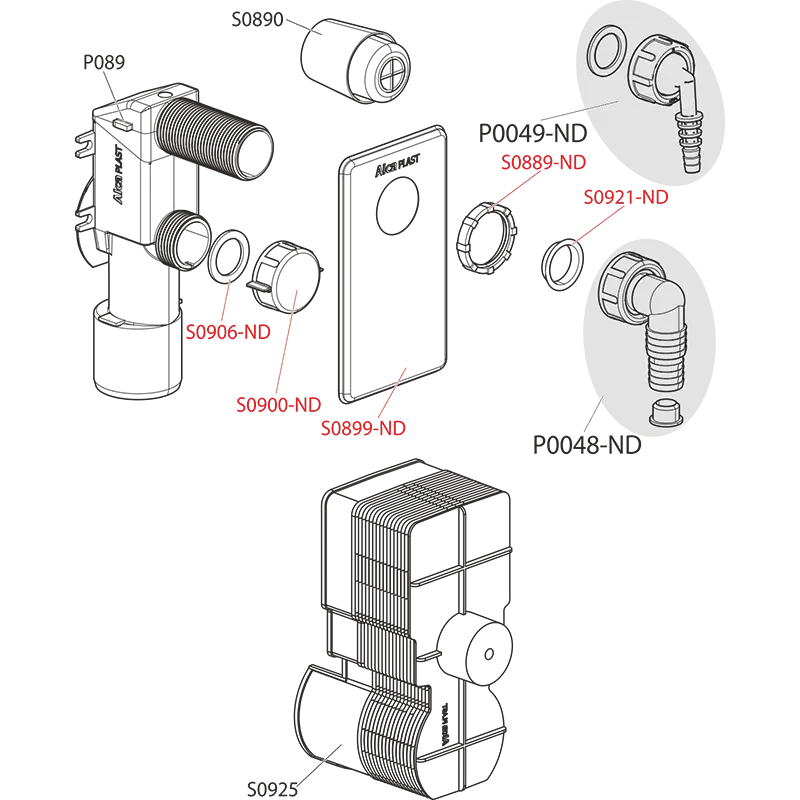
Modern Toilet Fixture with Flush System -

SMC Corporate Logo Design -
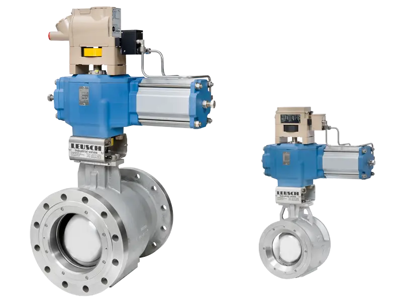
Industrial Valve System Design -

Black and White Gears Icons -
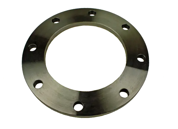
Metal Flange with Holes -

Compound Bow for Archery and Hunting Enthusiasts -
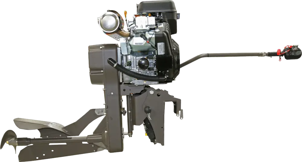
Powerful Engine Machinery -
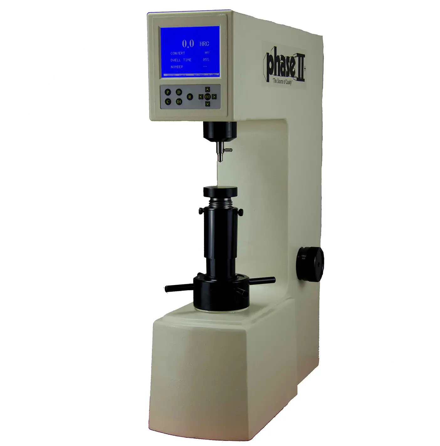
Precision Hardness Tester for Materials -
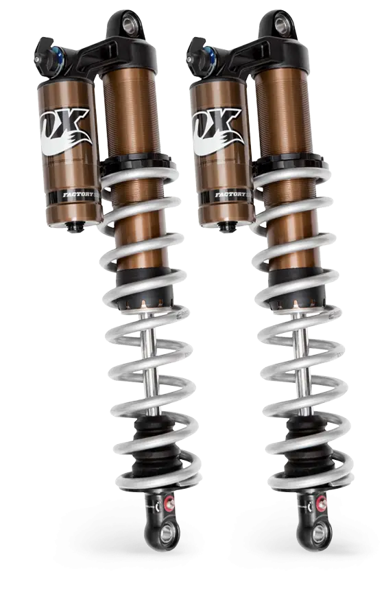
Fox Shock Absorbers for Off-road Vehicles -

Vintage Sewing Machine -

Set of Car Parts Icons -

Steampunk Mechanical Wings -
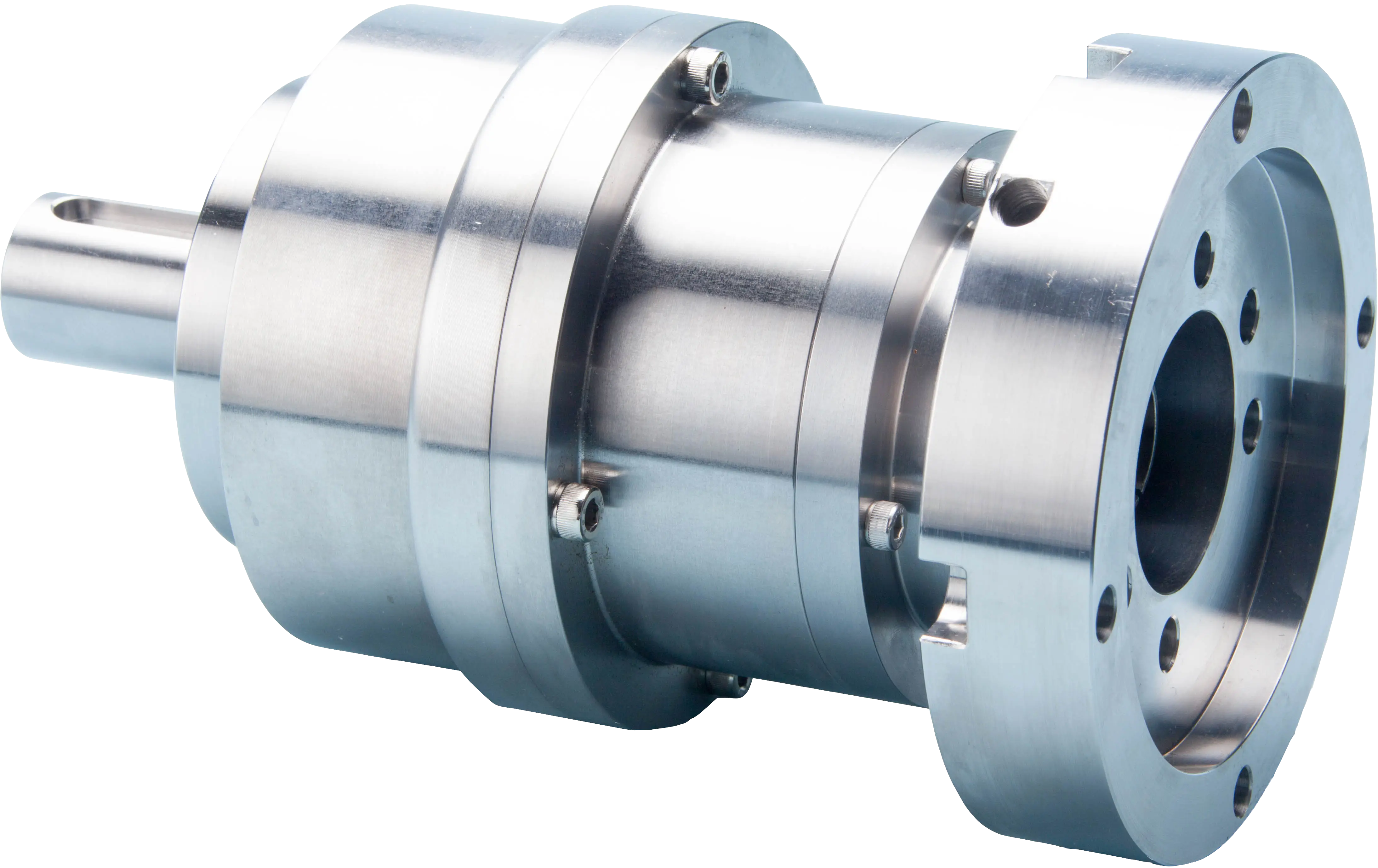
Precision Metal Gear Reducer for Industrial Use -

Colorful Oil Pump Jack -
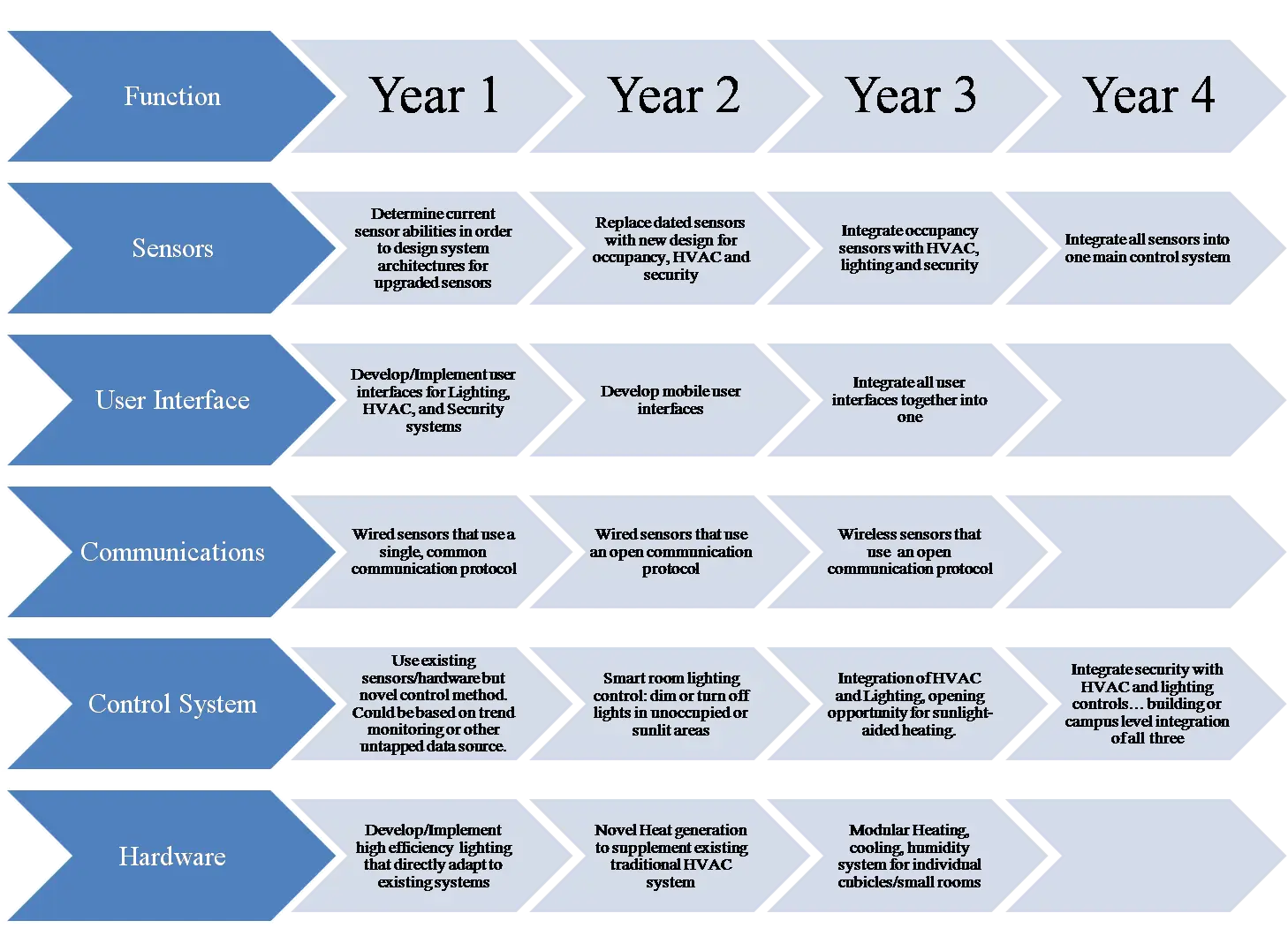
Development Roadmap for Project Planning -
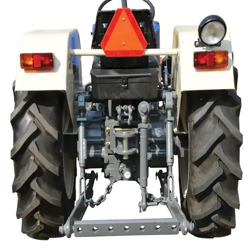
Back View of a Tractor for Agricultural Use -
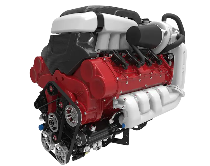
Powerful Engine Machine -
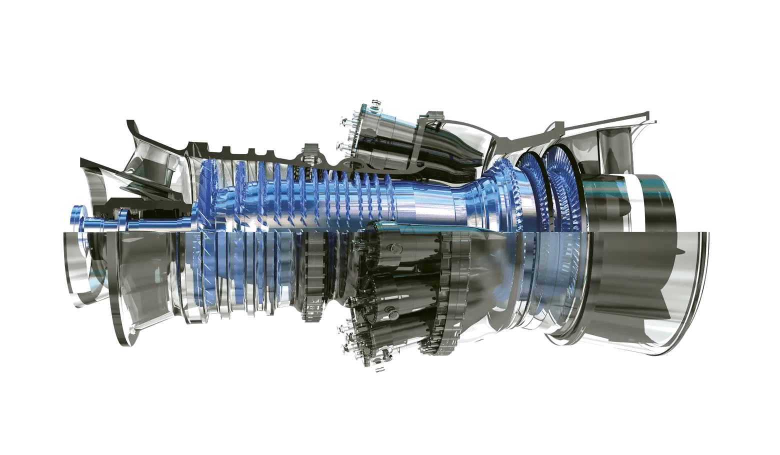
High-tech Engine Turbine System -
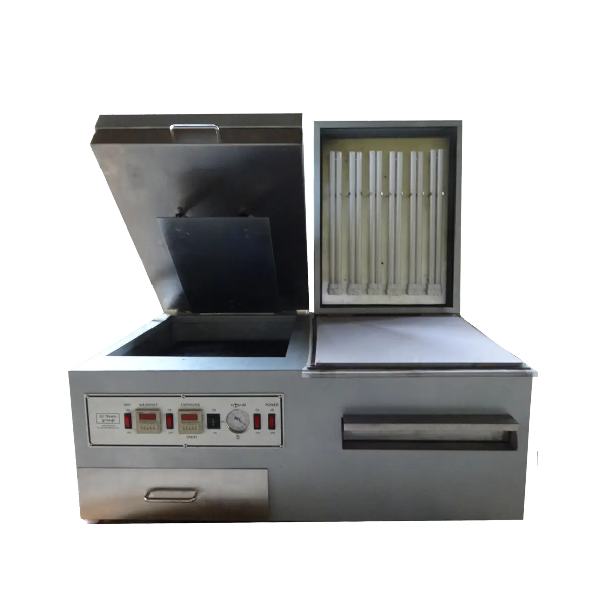
Industrial Machine for Manufacturing -
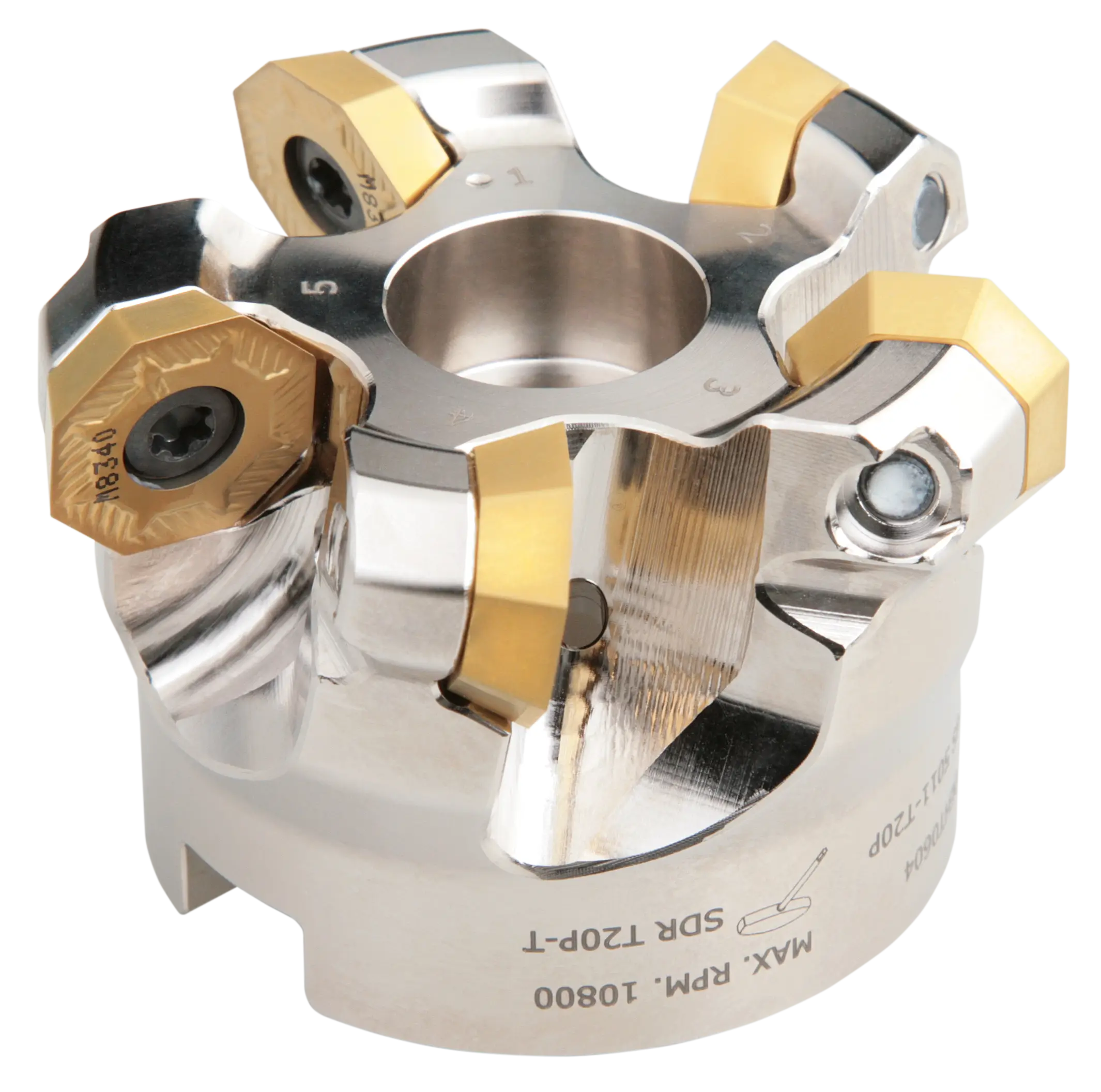
Industrial Milling Cutter -

Black Gear Silhouette -

Black Gear Icon Design -
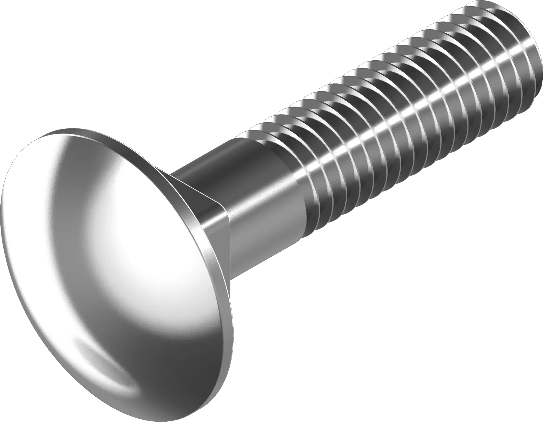
Metal Bolt for Fixing -
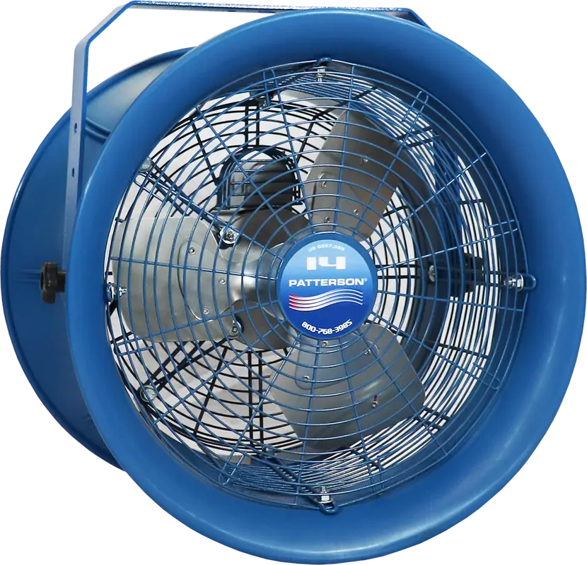
Blue Industrial Fan for Cooling -
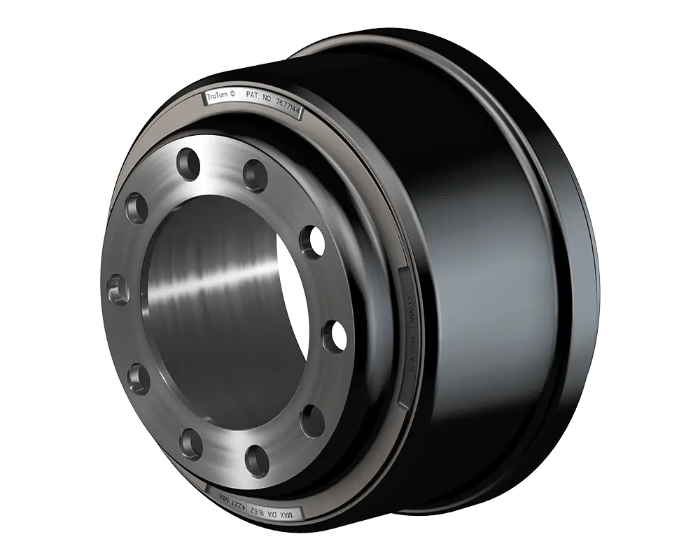
Industrial Metal Hub Component -
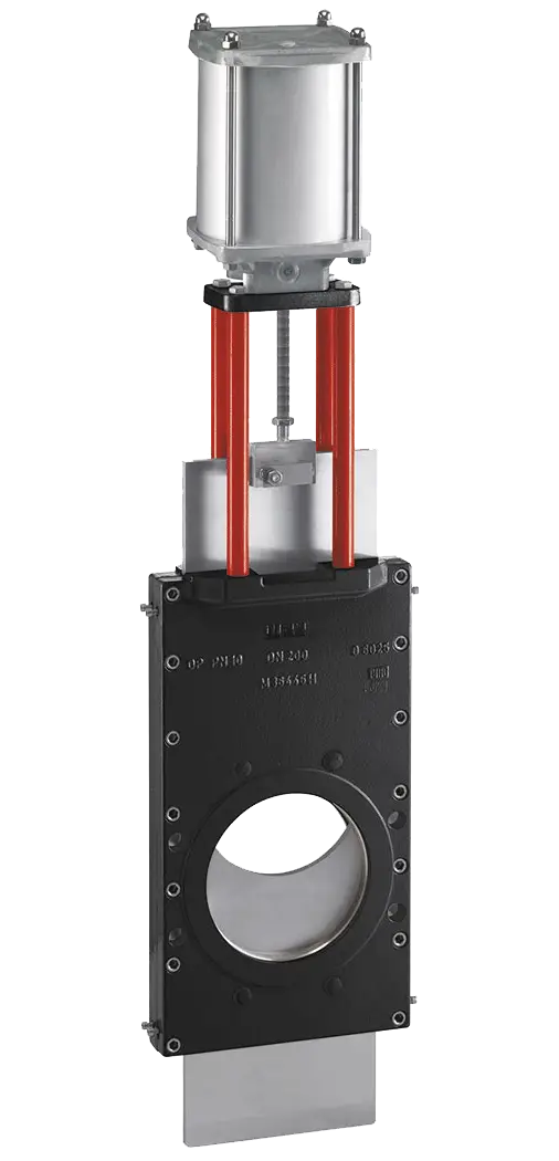
Heavy-Duty Gate Valve