You Might Like
-

Black and White Gears Icons -

Set of Car Parts Icons -

Wrench and Screwdriver Tools -
High-tech Engine Turbine System -

Gear Icon for Mechanical or System Settings -
Nexus Manager Flowchart -

Digestive System Diagram -
HR Workflow Diagram -

Artificial Intelligence Laptop Interface Illustration -

Gray Wrench Tool Illustration -

Detailed Lungs Diagram Illustration -
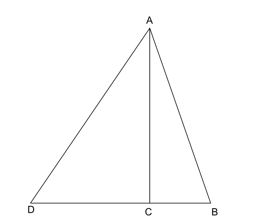
Triangle Diagram for Geometric Representation -
Durable Metal Wrench for Repairs -

Black Gear Mechanisms Symbol -
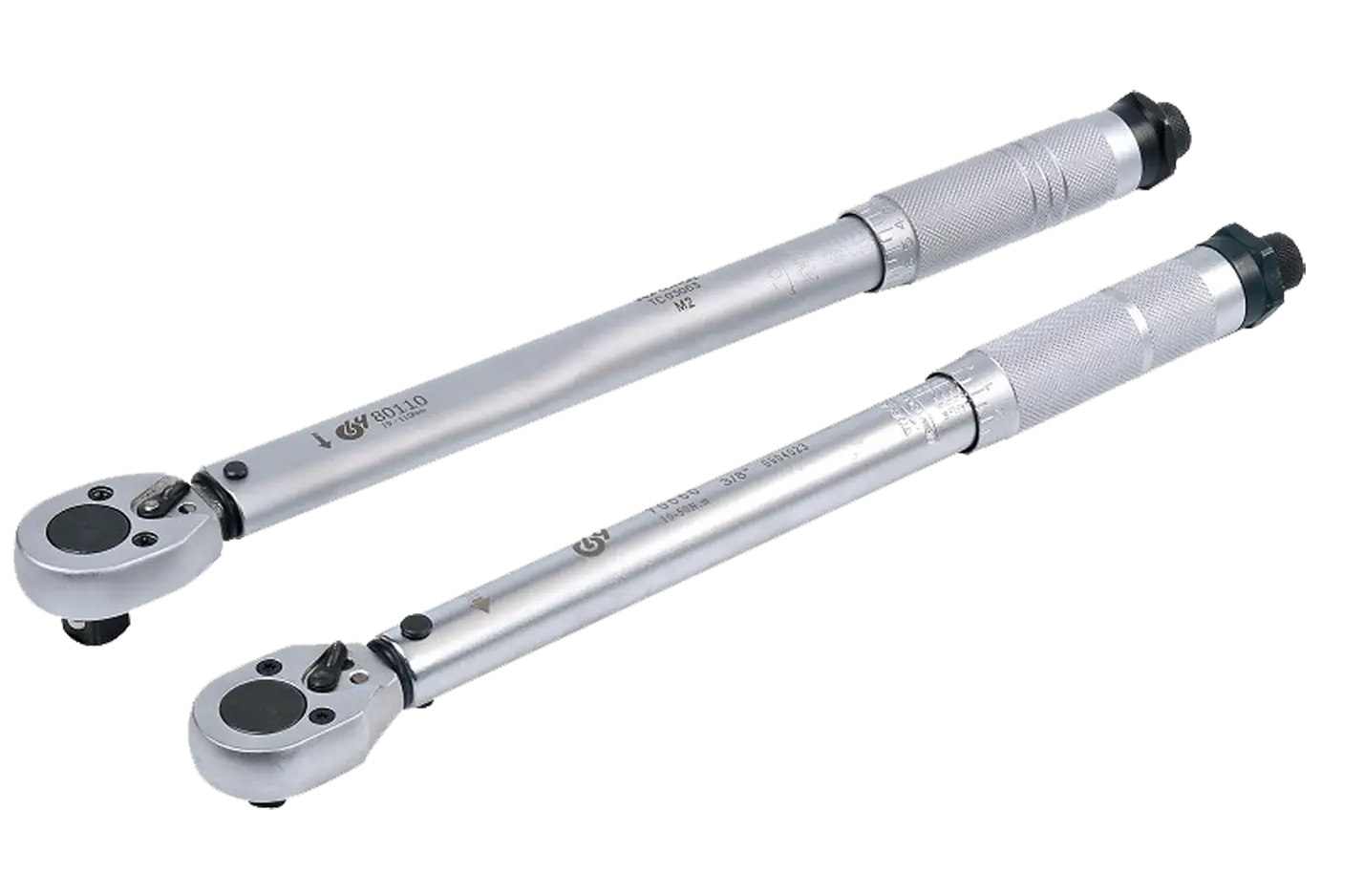
Adjustable Torque Wrenches for Precision Work -

Gear and Rack Mechanism Illustration -
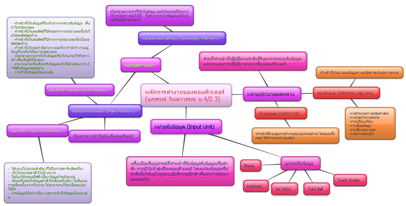
Mind Map Diagram in Colorful Design -
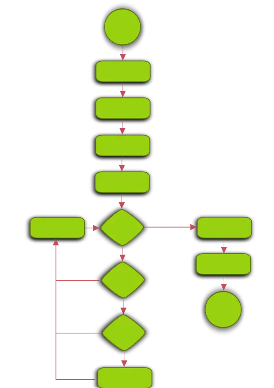
Green Flowchart Diagram -

Hex Key Tool -
Silhouette of Wrench and Screwdriver Tools -

Mathematical Network Diagram with Nodes and Lines -

Red Gear Icon for App and Settings -
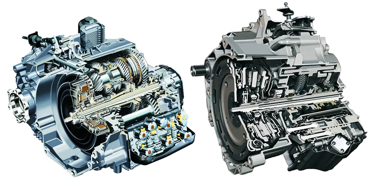
Detailed Car Engines -

Gear and Wrench Icon -
Wrench and Screwdriver for DIY Projects -
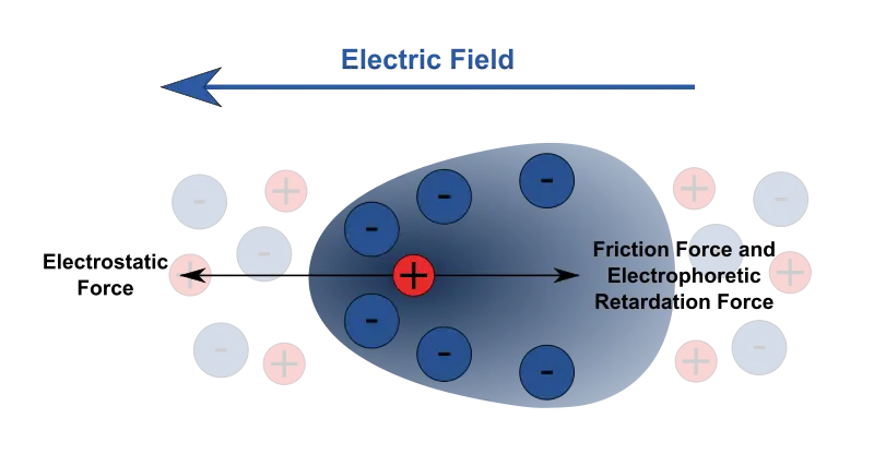
Electric Field and Electrostatic Force Diagram -
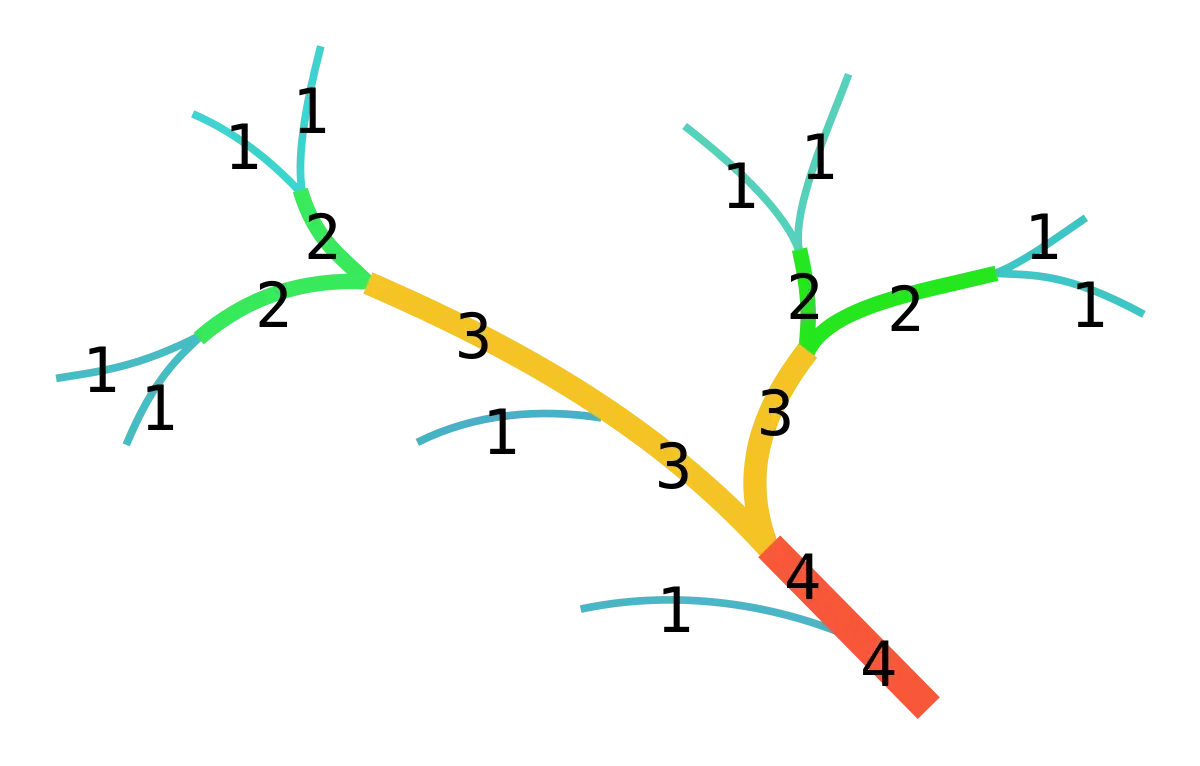
Tree Diagram with Numbers -

Futuristic Robotic Hand -
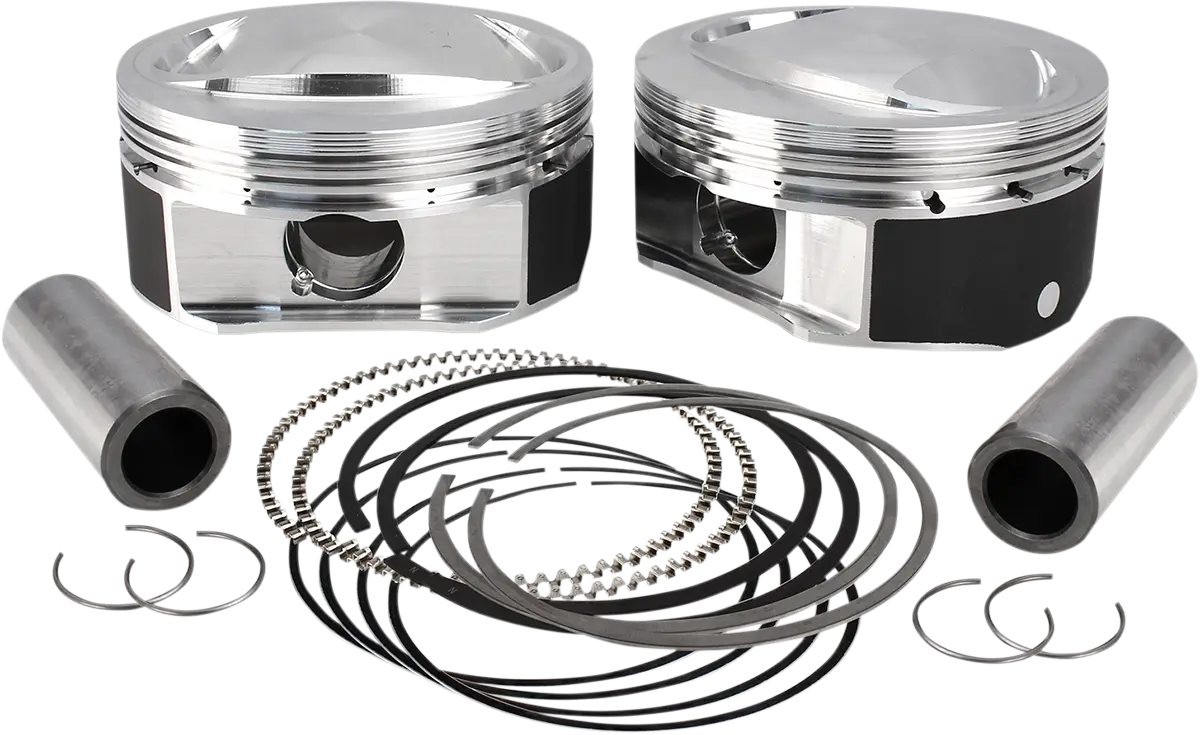
Automotive Piston Kit -

Steampunk Hourglass Timer