You Might Like
-
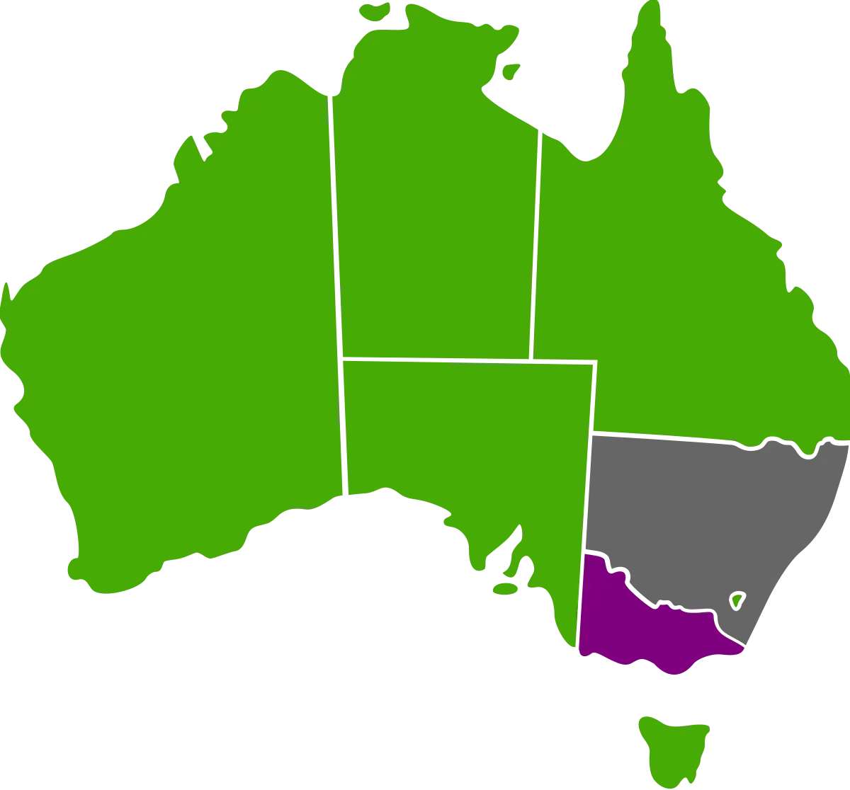
Australian Map with Regional Color Variations -
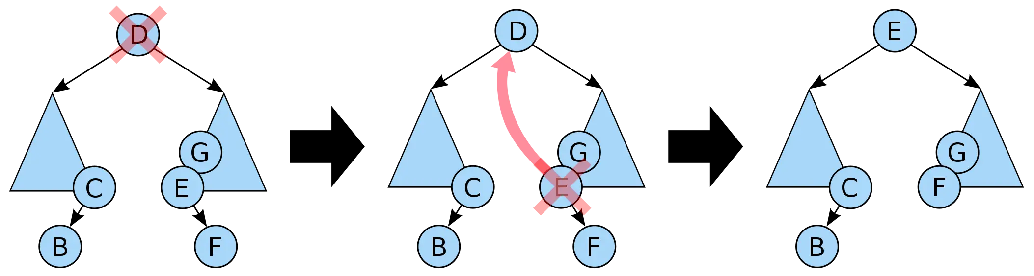
Binary Tree Node Deletion Illustrative Process -

Yellow and Black Robot -
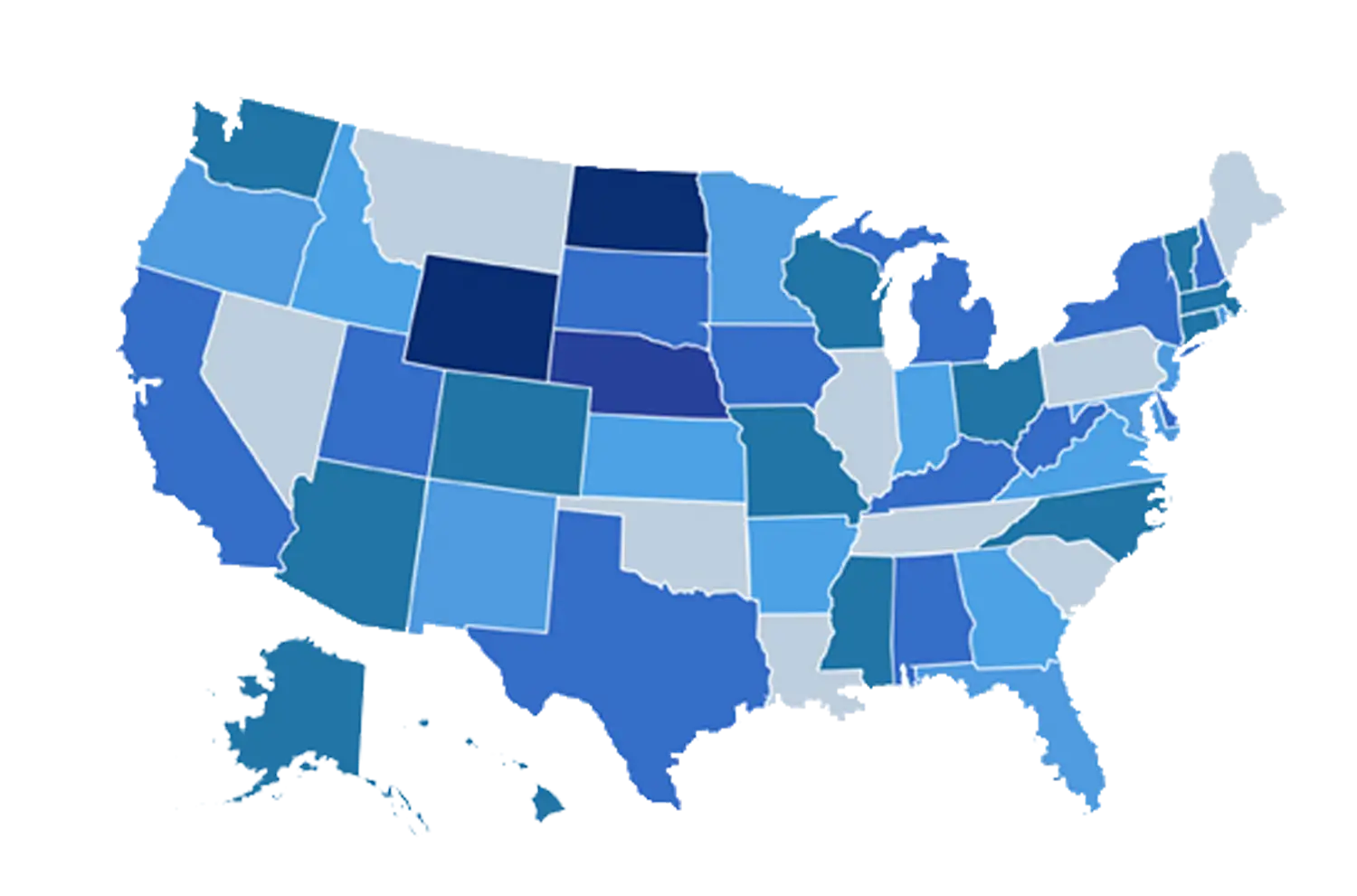
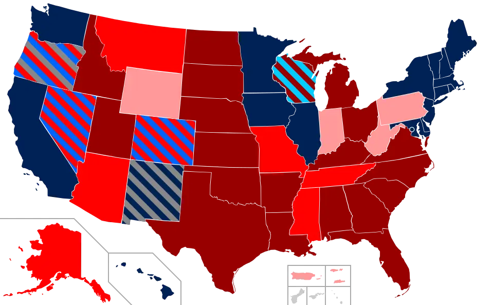
Blue Map of United States with States Highlighted -
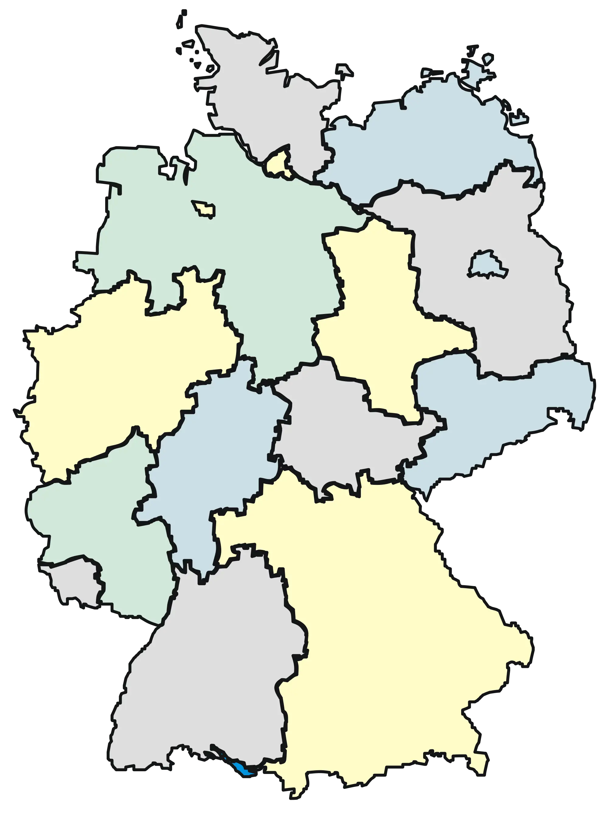
Illustrated Map of Germany with Regions -

Futuristic Metal Robot with Spikes -
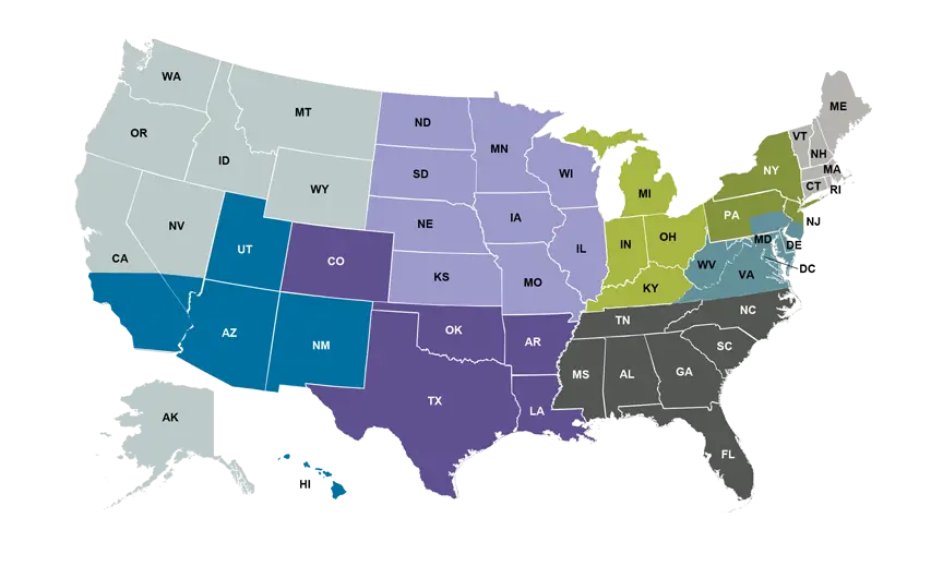
Colorful Map of USA Showing States by Regions -
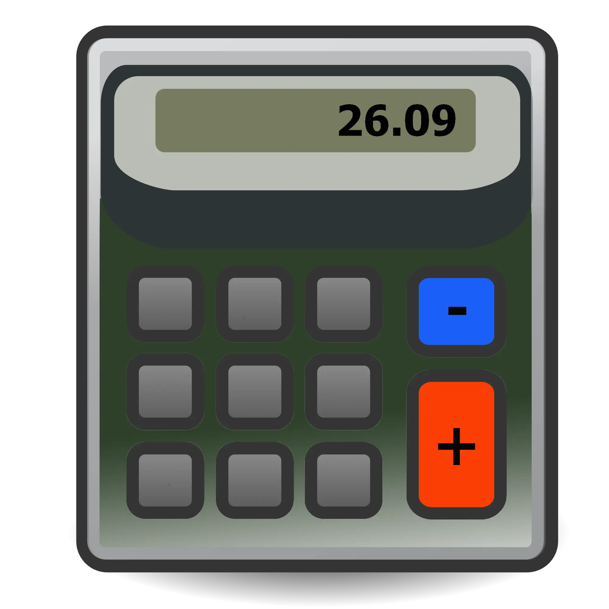
Digital Calculator Illustration -

Mathematical Lambda Symbol -
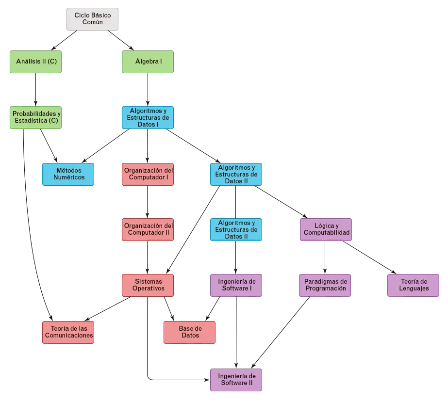
Flowchart Diagram Layout -
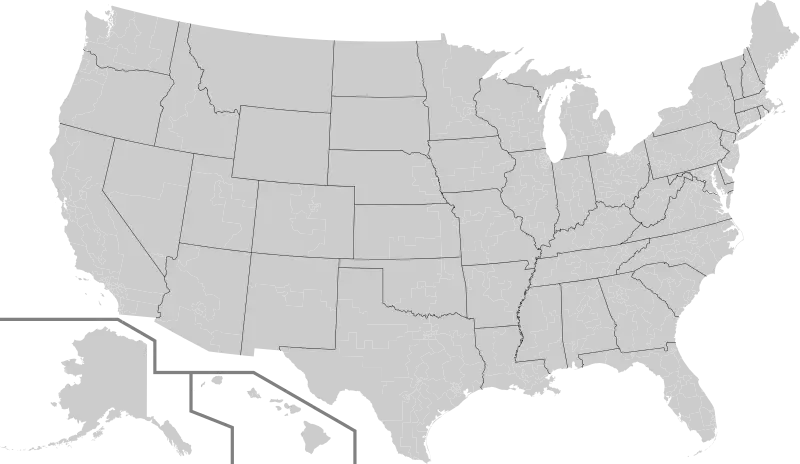
Gray USA Map with State Boundaries -
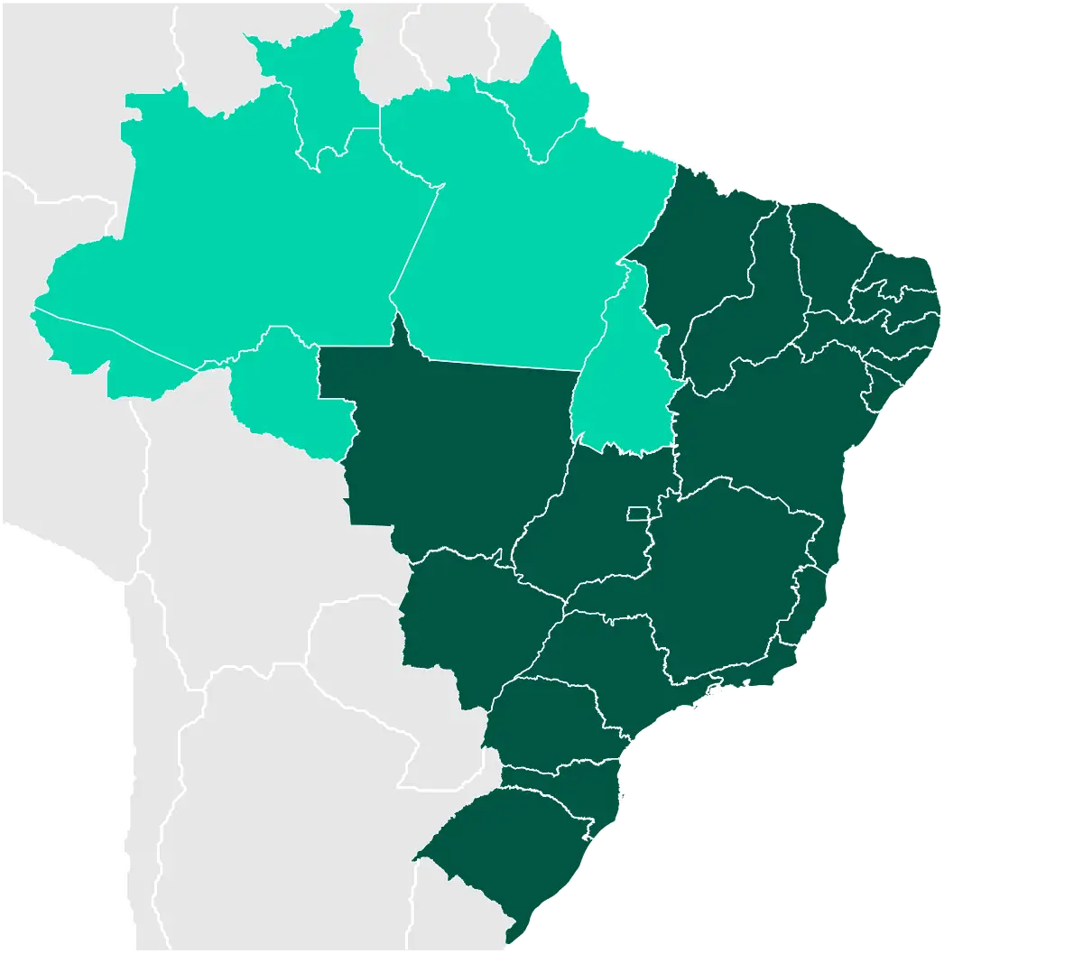
Map of Brazil -

Futuristic Red and White Robot Design -
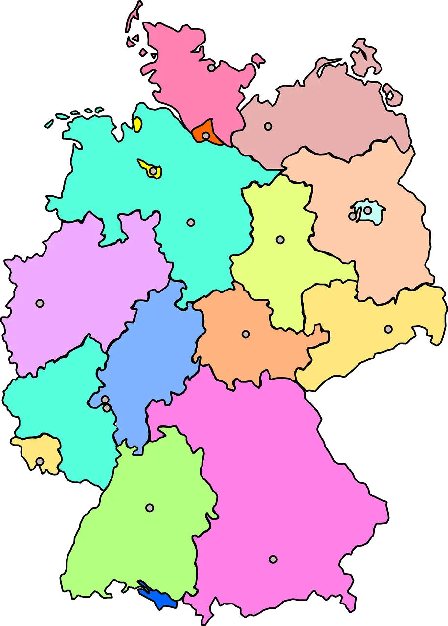
Colorful Map of Germany with Regions -
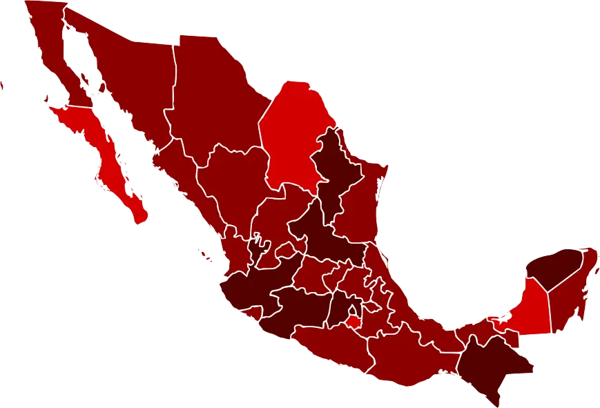
Map of Mexico with Regions Highlighted -
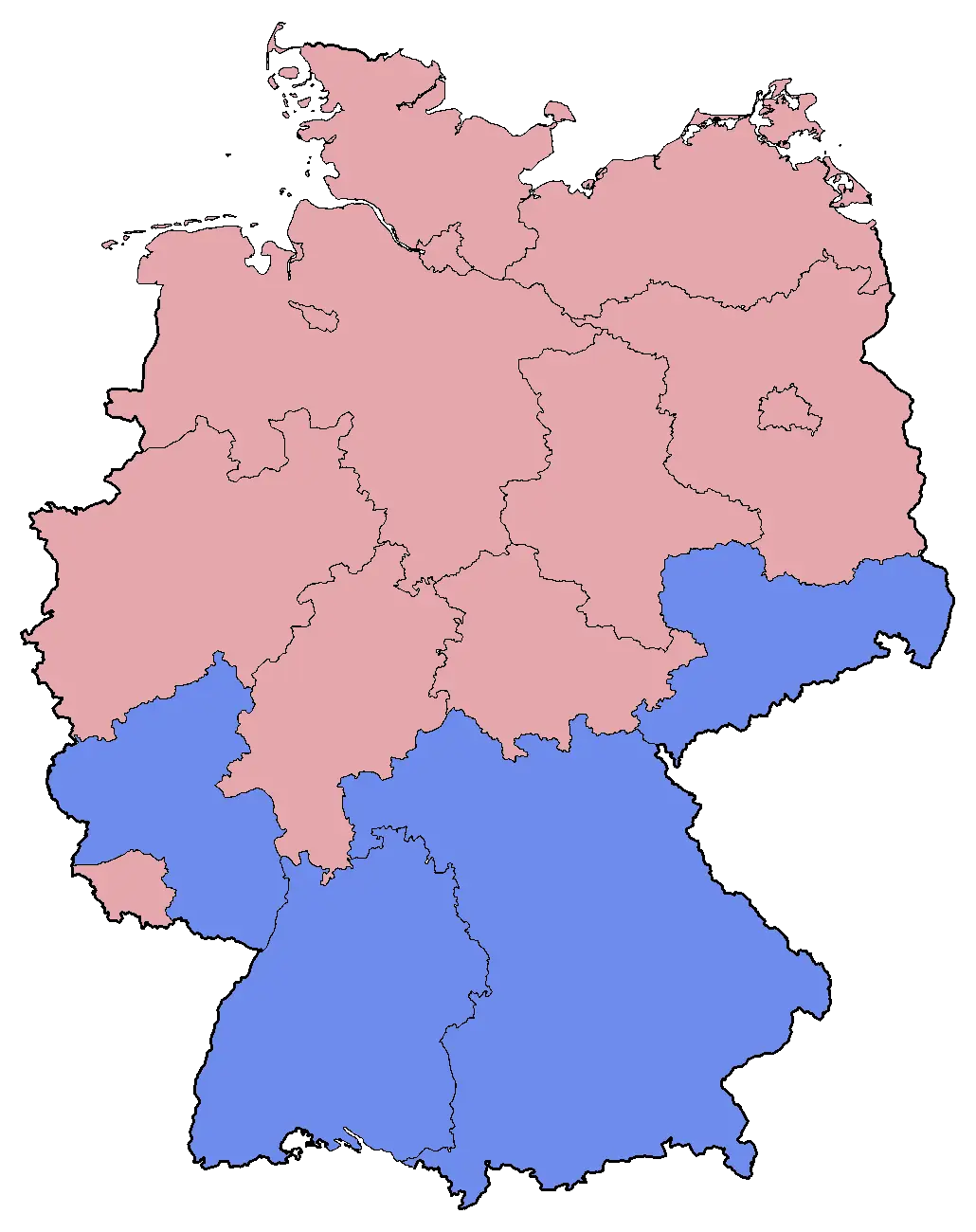
Colored Map of Germany with Regional Divisions -

Venn Diagram of Data Science -

Outline Map of the United States with State Borders -
Colored USA Map with State Divisions -
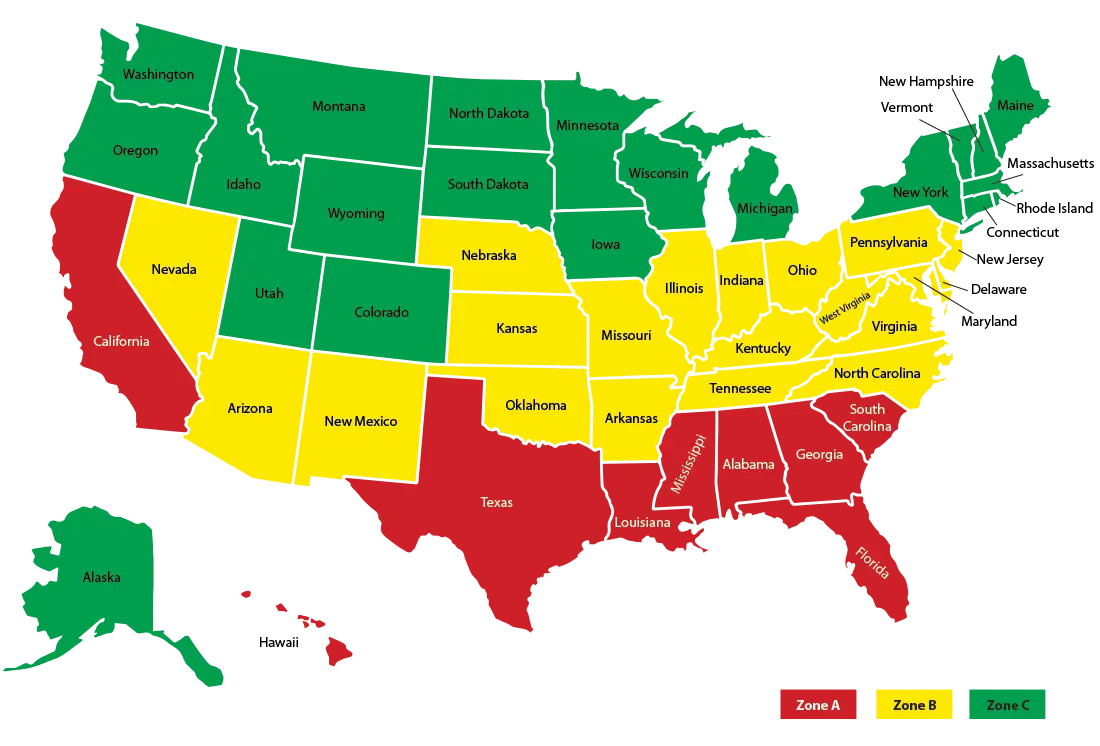
Color-Coded Map of the United States Regions -

Modern Digital Calculator for Arithmetic Operations -
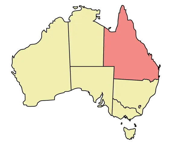
Outline and Region Illustration of Australia Map -

Golden Mechanical Lion -
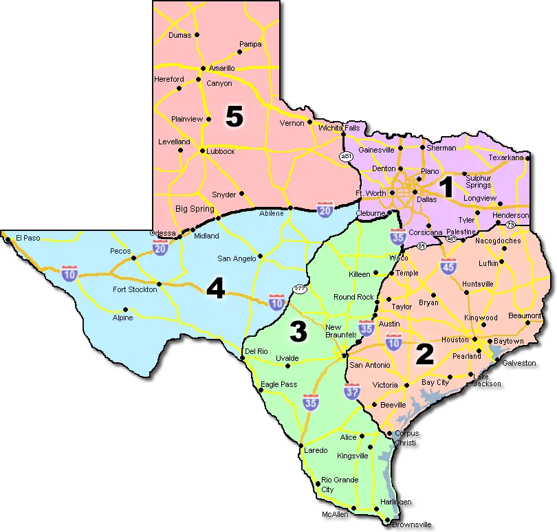
Map of Texas with Regions -
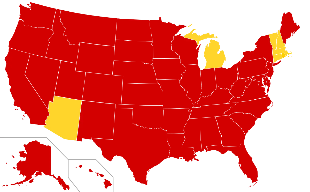
Red and Yellow USA Map Visualization -

Casio Digital Calculator -

Retro Robot with Visible Brain Interface -

Armored Robot Character -
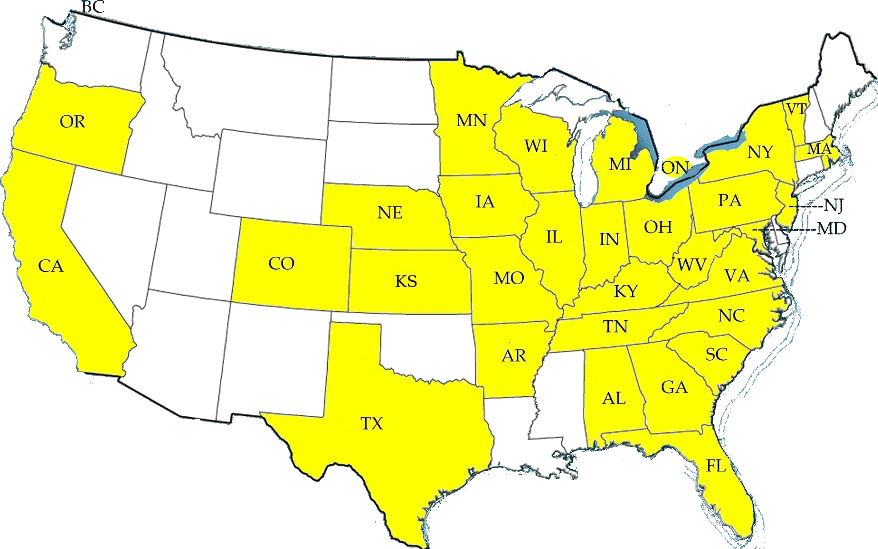
Map of USA with Highlighted States -
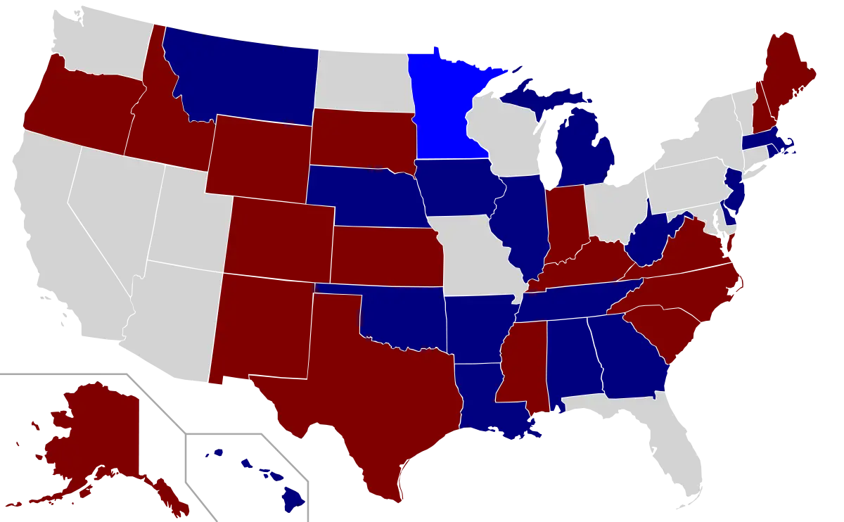
Color-Coded USA Political Map