You Might Like
-
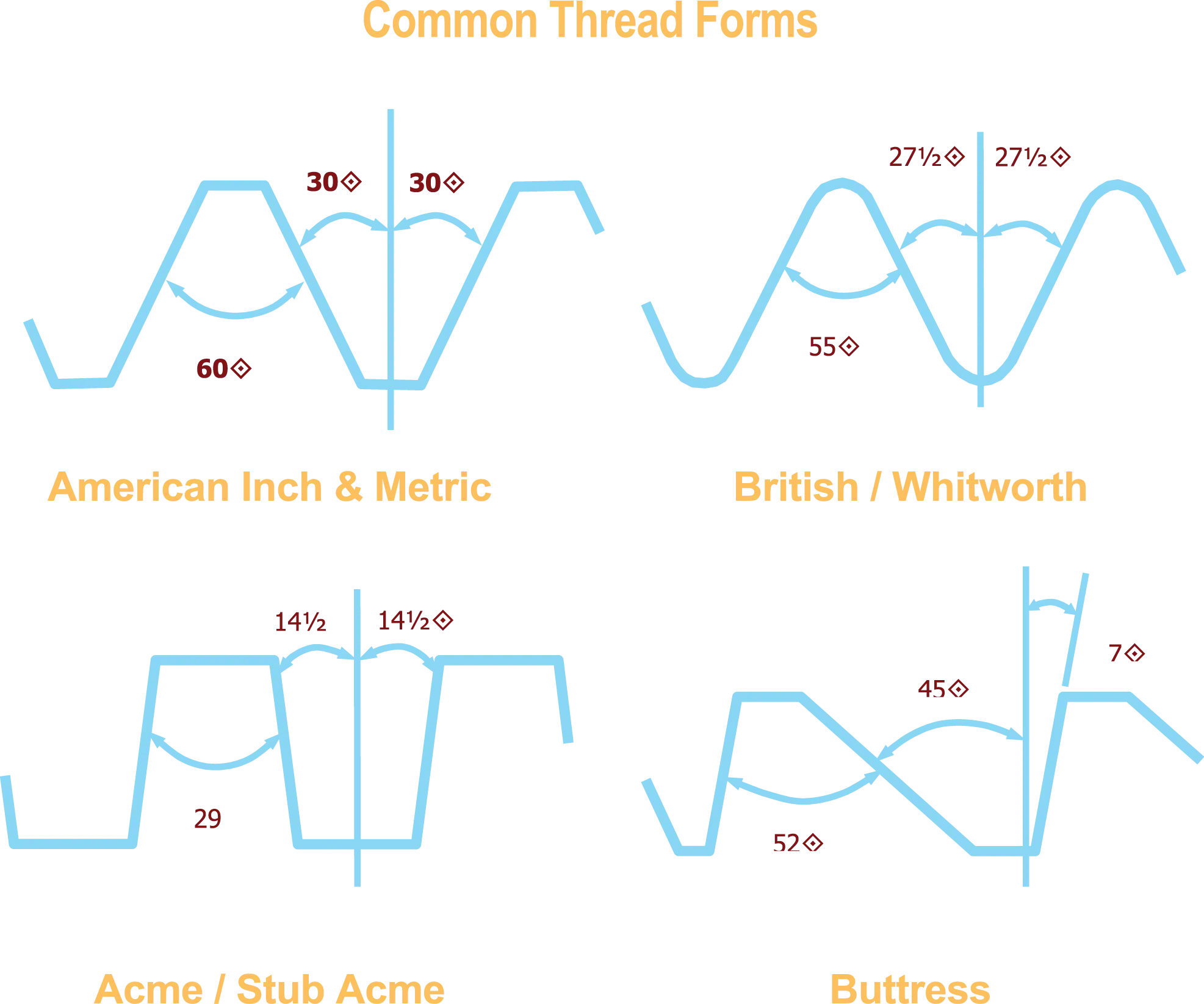
Common Thread Forms Diagram -

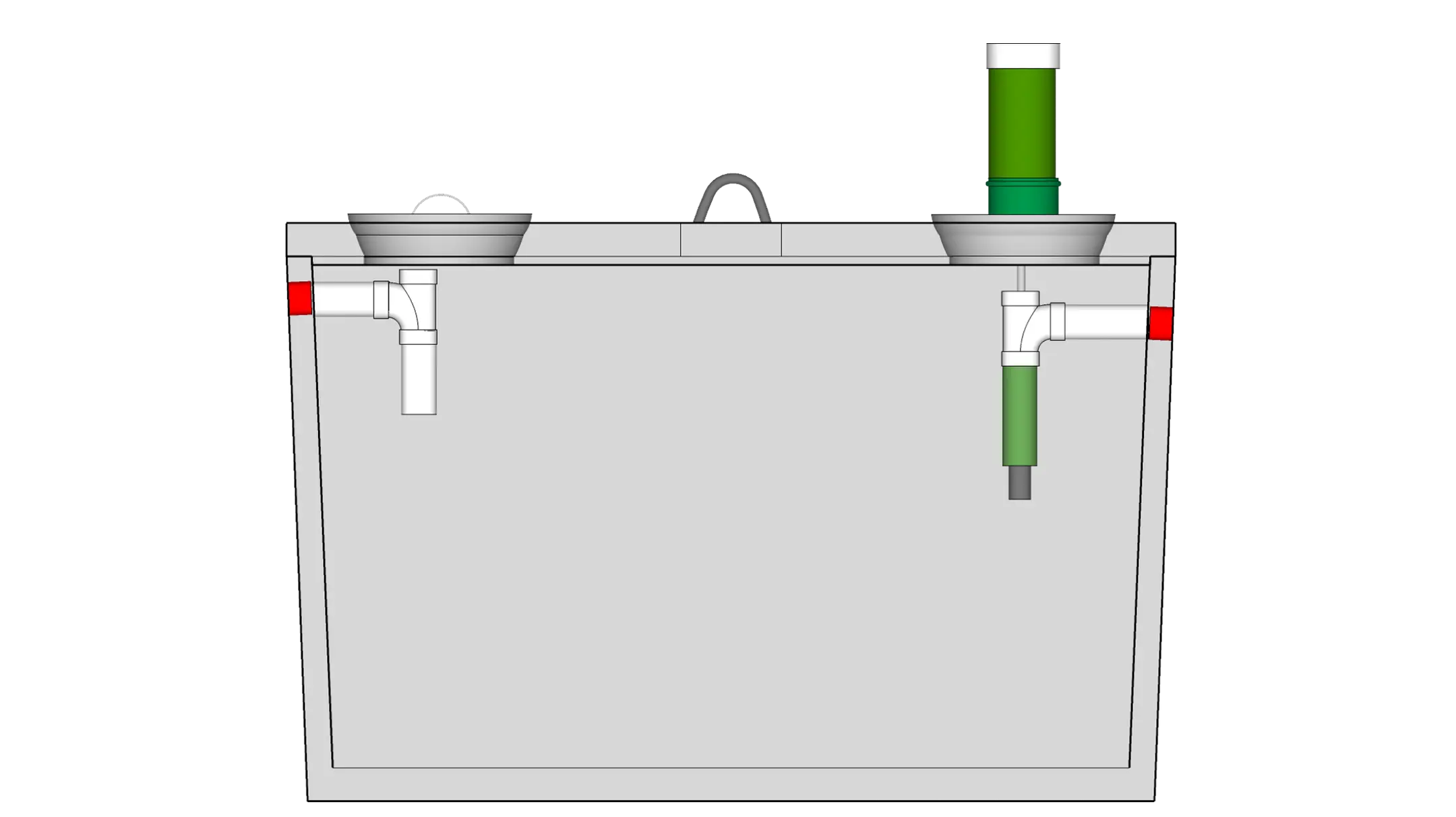
Large Water Tank for Storage -
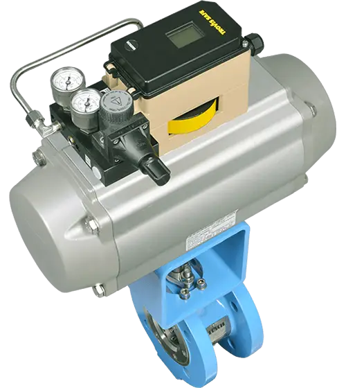
Industrial Valve Actuator for Automation -
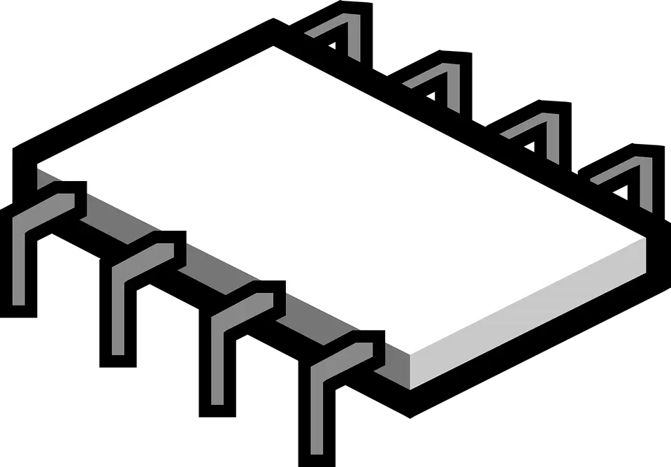
Microchip Illustration for Technology Concept -

Resistor Color Code Chart -
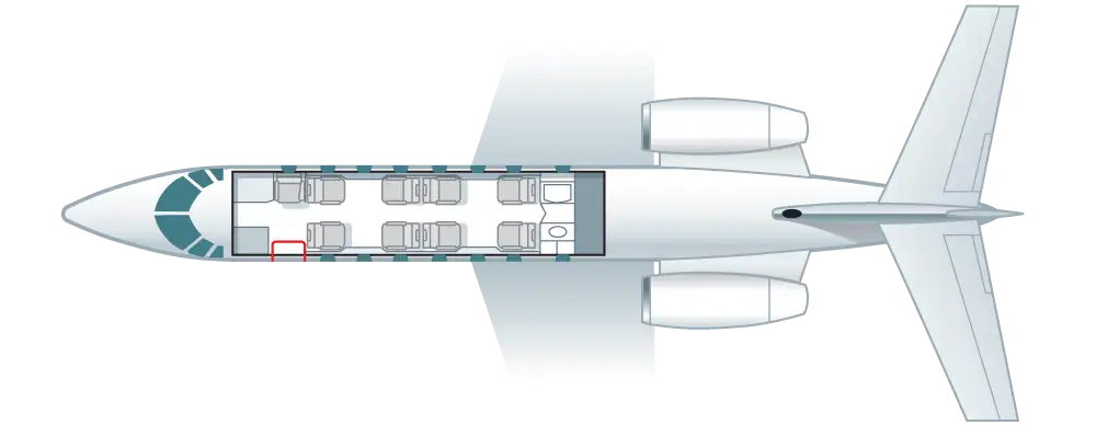
Airplane Seating Layout Blueprint -
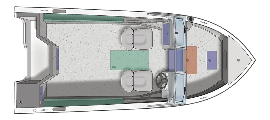
Top View of Boat Floor Plan Layout -
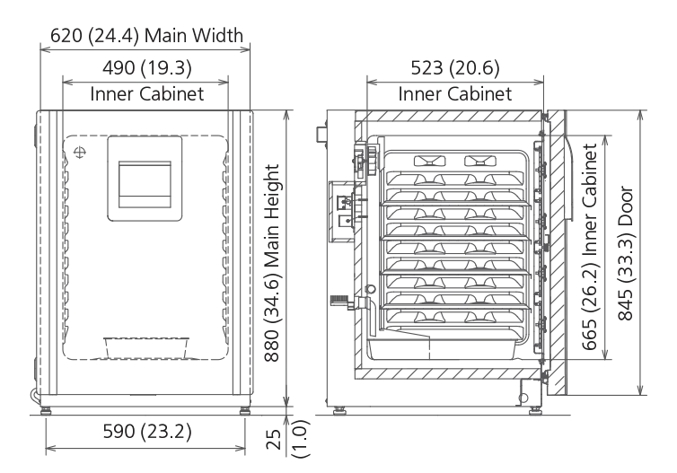
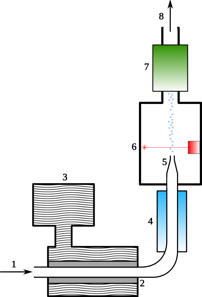
Technical Diagram of an Incubator -
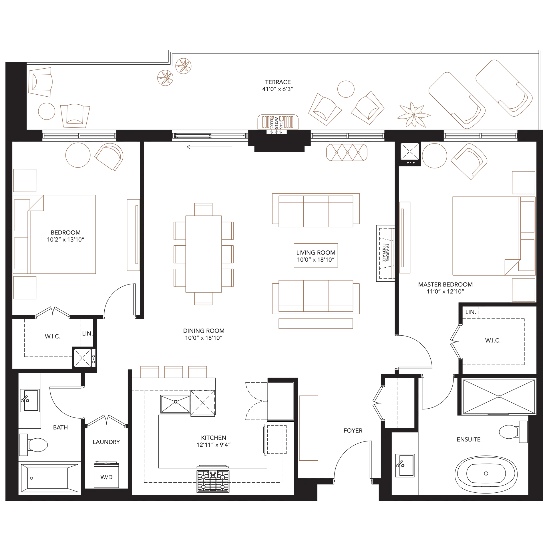
Apartment Floor Plan Illustration -

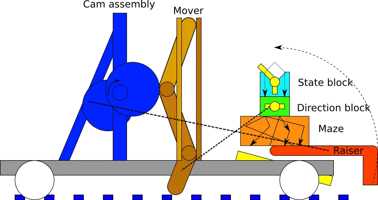
Assembly Diagram with Parts and Instructions -

Brown Mechanical Part -

Airplane Rotation Movement Diagram -

Thyristor Electronic Component Symbol -
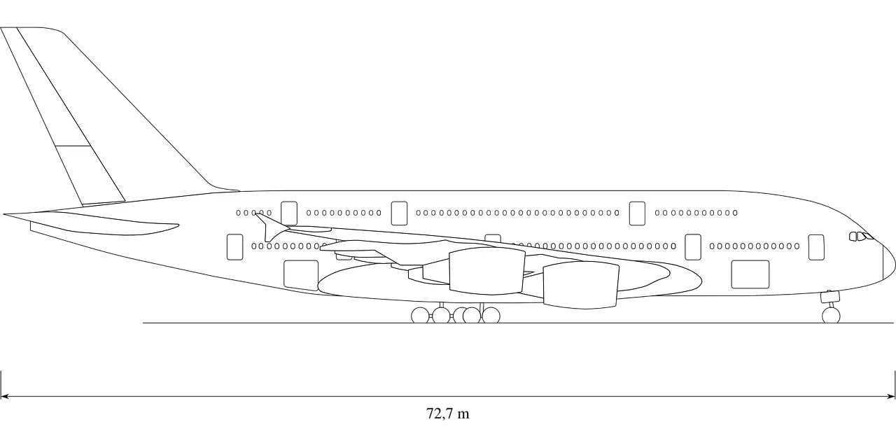
Airplane Blueprint Illustration for Design -

Photo Diode Circuit Symbol for Electronics -

Axonometry Diagram -
Mechanical Diagram Illustration -
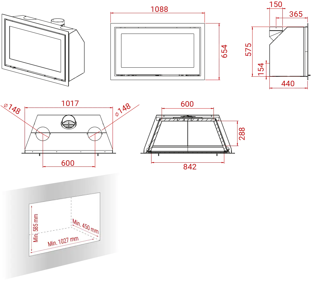
Technical Drawing with Measurements -

Detailed Manufacturing Process Infographic -

Black and White Circuit Board Design Illustration -

Electronic Devices Line Art -

Architectural Building Plan -

Wave and Coil Electrical Symbols -
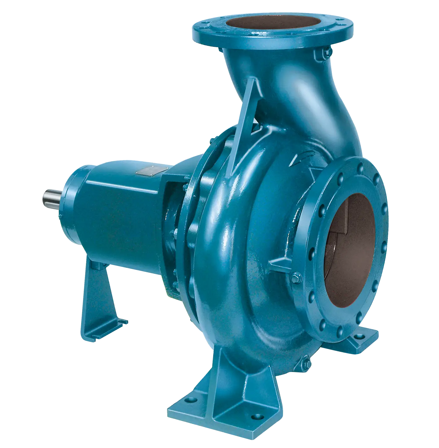
Blue Centrifugal Pump -
Modern Water Cooler Dispenser -
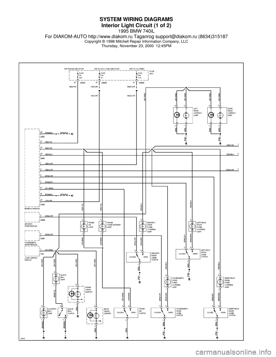
Wiring Diagram Schematic for Electrical System -
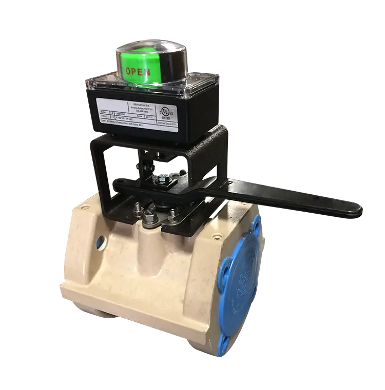
Industrial Control Valve -

White Siphon Tube for Fluid Transfer -

Bicycle Geometry Diagram for Technical Design -

Medical Transparent Tubing